


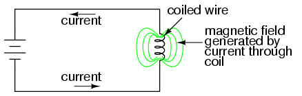
As we have already seen, the magnetic field produced by a current-carrying conductor can store energy. This storage of energy translates to an opposition to changes in current through that conductor. Called "inductance," this effect can be made more pronounced by forming the conductor into a coil, and/or providing a path of high magnetic permeability for the magnetic field to develop.
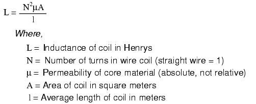
An approximate figure for an inductor's inductance can be found using this equation:
We also know that an inductor exposed to a changing magnetic field will develop a voltage across its length. The inductor's opposition to changes in current is a manifestation of this effect, the induced voltage produced by the change in its own magnetic field strength producing a voltage which tries to maintain current at that same magnitude and in that same direction. This is called "self-induction." The greater the inductor's inductance (measured in the unit of Henrys), the more self-induced voltage will be produced for a given rate of current change over time.
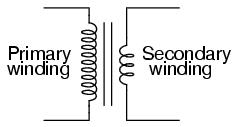
It should stand to reason, then, that if a changing magnetic field produced by one inductor carrying alternating current were to "link" with the turns of wire in another inductor, it would induce an AC voltage in the unpowered inductor. This is definitely the case, and the phenomenon is called mutual inductance. A device constructed to exploit this effect is called a transformer. The symbol for a transformer looks like this:
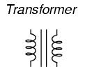
The two inductor coils are easily distinguished in the above symbol. The pair of vertical lines represent an iron core common to both inductors. While many transformers have ferromagnetic core materials, there are some that do not, their constituent inductors being magnetically linked together through the air.
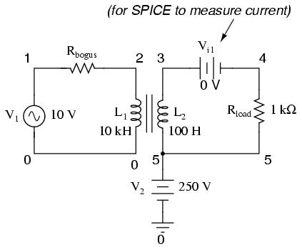
The following photograph shows two inductor coils wound around an iron core. While most transformer designs enclose the coils and core in a metal frame for protection, this device is open for viewing and so serves its illustrative purpose well:
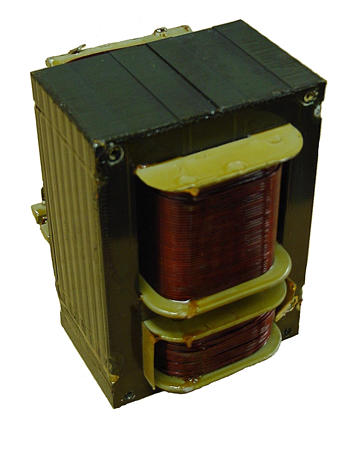
Both coils of wire can be seen here with copper-colored varnish insulation. The top coil is larger than the bottom coil, having a greater number of "turns" around the core.
By having two inductors coupled together by a common magnetic field path, it is possible to transfer energy from one inductor circuit to the other, rather than just store energy in the magnetic field. In order for this to work, of course, the magnetic field has to be constantly changing in strength, otherwise no voltage will be induced in the unpowered coil. Thus, the transformer is essentially an alternating current (AC) device.
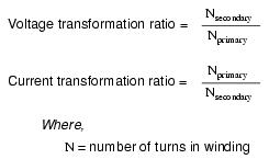
In transformers, the inductor coils are often referred to as windings, in reference to the manufacturing process where wire is wound around the core material. The powered inductor of a transformer is called the primary winding, while the unpowered coil is called the secondary winding. It is easy to demonstrate simple transformer action using SPICE, setting up the primary and secondary windings of the simulated transformer as a pair of "mutual" inductors. The coefficient of magnetic field coupling is given at the end of the "k" line in the SPICE circuit description, this example being set very nearly at perfection (1.000). This coefficient describes how closely "linked" the two inductors are, magnetically. The better these two inductors are magnetically coupled, the more efficient the energy transfer between them should be.
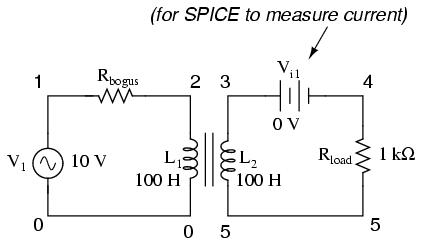
transformer
v1 1 0 ac 10 sin
rbogus1 1 2 1e-12   required to satisfy a quirk of SPICE
rbogus2 5 0 9e12    ditto
l1 2 0 100
l2 3 5 100
k l1 l2 0.999       This line tells SPICE that the two inductors
vi1 3 4 ac 0        l1 and l2 are magnetically "linked" together
rload 4 5 1k
.ac lin 1 60 60
.print ac v(2,0) i(v1)
.print ac v(3,5) i(vi1)
.end
freq          v(2)        i(v1)
6.000E+01     1.000E+01   9.975E-03   Primary winding
freq          v(3,5)      i(vi1)
6.000E+01     9.962E+00   9.962E-03   Secondary winding
Note that with equal inductances for both windings (100 Henrys each), the AC voltages and currents are nearly equal for the two. What you are seeing here is quite typical of transformer efficiency. Anything less than 95% efficiency is considered poor for modern power transformer designs, and this transfer of power occurs with no moving parts or other components subject to wear.
If we decrease the load resistance so as to draw more current with the same amount of voltage, we see that the current through the primary winding increases in response. Even though the AC power source is not directly connected to the load resistance (rather, it is electromagnetically "coupled"), the amount of current drawn from the source will be almost the same as the amount of current that would be drawn if the load were directly connected to the source. Take a close look at the next two SPICE simulations, showing what happens with different values of load resistors:
transformer
v1 1 0 ac 10 sin
rbogus1 1 2 1e-12
rbogus2 5 0 9e12
l1 2 0 100
l2 3 5 100
k l1 l2 0.999
vi1 3 4 ac 0
rload 4 5 200       Note load resistance value of 200 ohms
.ac lin 1 60 60
.print ac v(2,0) i(v1)
.print ac v(3,5) i(vi1)
.end
freq          v(2)        i(v1)
6.000E+01     1.000E+01   4.679E-02
freq          v(3,5)      i(vi1)
6.000E+01     9.348E+00   4.674E-02
transformer
v1 1 0 ac 10 sin
rbogus1 1 2 1e-12
rbogus2 5 0 9e12
l1 2 0 100
l2 3 5 100
k l1 l2 0.999
vi1 3 4 ac 0
rload 4 5 15
.ac lin 1 60 60
.print ac v(2,0) i(v1)
.print ac v(3,5) i(vi1)
.end
freq          v(2)        i(v1)
6.000E+01     1.000E+01   1.301E-01
freq          v(3,5)      i(vi1)
6.000E+01     1.950E+00   1.300E-01
Our load current is now 0.13 amps, or 130 mA, which is substantially higher than the last time. The primary current is very close to being the same, but notice how the secondary voltage has fallen well below the primary voltage (1.95 volts versus 10 volts at the primary). The reason for this is our transformer design: the windings have too much inductance (100 Henrys each), and therefore too much inductive reactance (impedance) to allow for these high currents. If we change the design to have less inductance, the figures for voltage between primary and secondary windings will be much closer to being equal again:
transformer
v1 1 0 ac 10 sin
rbogus1 1 2 1e-12
rbogus2 5 0 9e12
l1 2 0 1            1 henry rather than 100 henrys
l2 3 5 1            1 henry rather than 100 henrys
k l1 l2 0.999
vi1 3 4 ac 0
rload 4 5 15
.ac lin 1 60 60
.print ac v(2,0) i(v1)
.print ac v(3,5) i(vi1)
.end
freq          v(2)        i(v1)
6.000E+01     1.000E+01   6.664E-01
freq          v(3,5)      i(vi1)
6.000E+01     9.977E+00   6.652E-01
Here we see that our secondary voltage is back to being nearly equal with the primary, and the secondary current, as usual, is nearly equal to the primary current as well. The question naturally arises at this point: if excessive inductance was a problem, then why not design all transformers with as little inductance as possible? The answer to this question can be found in the next SPICE simulation, taking the low-inductance transformer we just created and using it to transfer power to a higher resistance load (back up to 1 kΩ as in the first demonstration):
transformer
v1 1 0 ac 10 sin
rbogus1 1 2 1e-12
rbogus2 5 0 9e12
l1 2 0 1
l2 3 5 1
k l1 l2 0.999
vi1 3 4 ac 0
rload 4 5 1k
.ac lin 1 60 60
.print ac v(2,0) i(v1)
.print ac v(3,5) i(vi1)
.end
freq          v(2)        i(v1)
6.000E+01     1.000E+01   2.835E-02
freq          v(3,5)      i(vi1)
6.000E+01     9.990E+00   9.990E-03
With lower winding inductances, the primary and secondary voltages are closer to being equal, but the primary and secondary currents are not. In this particular case, the primary current is 28.35 mA while the secondary current is only 9.990 mA: almost three times as much current in the primary as the secondary. Why is this? With less inductance in the primary winding, there is less inductive reactance, less impedance to hold back current. A substantial amount of the current through the primary winding is due to that winding's reactance alone and not the transfer of power to the secondary winding and load.
An ideal transformer with identical primary and secondary windings would manifest equal voltage and current in both sets of windings. In a perfect world transformers would transfer electrical power from primary to secondary as smoothly as though the load were directly connected to the primary power source, with no transformer there at all, but as you can see this ideal goal cannot be met by any one transformer design under all operating conditions. Transformers must be designed to operate within certain expected ranges of voltages and loads in order to perform as close to ideal as possible. For now, the most important thing to keep in mind is a transformer's basic operating principle: the transfer of power from the primary to the secondary circuit via electromagnetic coupling.
So far, we've observed simulations of transformers where the primary and secondary windings were of identical inductance, giving approximately equal voltage and current levels in both circuits. Equality of voltage and current between the primary and secondary sides of a transformer, however, is not the norm for all transformers. If the inductances of the two windings are not equal, something interesting happens:
transformer
v1 1 0 ac 10 sin
rbogus1 1 2 1e-12
rbogus2 5 0 9e12
l1 2 0 10000
l2 3 5 100
k l1 l2 0.999
vi1 3 4 ac 0
rload 4 5 1k
.ac lin 1 60 60
.print ac v(2,0) i(v1)
.print ac v(3,5) i(vi1)
.end
freq          v(2)        i(v1)
6.000E+01     1.000E+01   9.975E-05    Primary winding
freq          v(3,5)      i(vi1)
6.000E+01     9.962E-01   9.962E-04    Secondary winding
Notice how the secondary voltage is approximately ten times less than the primary voltage (0.9962 volts compared to 10 volts), while the secondary current is approximately ten times greater (0.9962 mA compared to 0.09975 mA). What we have here is a device that steps voltage down by a factor of ten and current up by a factor of ten:
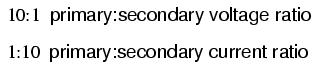
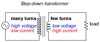
What we have here is a very useful device, indeed. With it, we can easily multiply or divide voltage and current in AC circuits. Indeed, the transformer has made long-distance transmission of electric power a practical reality, as AC voltage can be "stepped up" and current "stepped down" for reduced wire resistance power losses along power lines connecting generating stations with loads. At either end (both the generator and at the loads), voltage levels are reduced by transformers for safer operation and less expensive equipment. A transformer that increases voltage from primary to secondary (more secondary winding turns than primary winding turns) is called a step-up transformer. Conversely, a transformer designed to do just the opposite is called a step-down transformer.
In case you were wondering, it is possible to operate either of these transformer types backwards (powering the secondary winding with an AC source and letting the primary winding power a load) to perform the opposite function: a step-up can function as a step-down and visa-versa. However, as we saw in the first section of this chapter, efficient operation of a transformer requires that the individual winding inductances be engineered for specific operating ranges of voltage and current, so if a transformer is to be used "backwards" like this it must be employed within the original design parameters of voltage and current for each winding, lest it prove to be inefficient (or lest it be damaged by excessive voltage or current!).
Transformers are often constructed in such a way that it is not obvious which wires lead to the primary winding and which lead to the secondary. One convention used in the electric power industry to help alleviate confusion is the use of "H" designations for the higher-voltage winding (the primary winding in a step-down unit; the secondary winding in a step-up) and "X" designations for the lower-voltage winding. Therefore, a simple power transformer will have wires labeled "H1", "H2", "X1", and "X2". There is usually significance to the numbering of the wires (H1 vs. H2, etc.), which we'll explore a little later in this chapter.
The fact that voltage and current get "stepped" in opposite directions (one up, the other down) makes perfect sense when you recall that power is equal to voltage times current, and realize that transformers cannot produce power, only convert it. Any device that could output more power than it took in would violate the Law of Energy Conservation in physics, namely that energy cannot be created or destroyed, only converted. As with the first transformer example we looked at, power transfer efficiency is very good from the primary to the secondary sides of the device.
The practical significance of this is made more apparent when an alternative is considered: before the advent of efficient transformers, voltage/current level conversion could only be achieved through the use of motor/generator sets. A drawing of a motor/generator set reveals the basic principle involved:
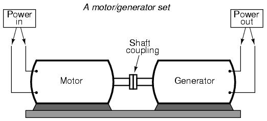
In such a machine, a motor is mechanically coupled to a generator, the generator designed to produce the desired levels of voltage and current at the rotating speed of the motor. While both motors and generators are fairly efficient devices, the use of both in this fashion compounds their inefficiencies so that the overall efficiency is in the range of 90% or less. Furthermore, because motor/generator sets obviously require moving parts, mechanical wear and balance are factors influencing both service life and performance. Transformers, on the other hand, are able to convert levels of AC voltage and current at very high efficiencies with no moving parts, making possible the widespread distribution and use of electric power we take for granted.
In all fairness it should be noted that motor/generator sets have not necessarily been obsoleted by transformers for all applications. While transformers are clearly superior over motor/generator sets for AC voltage and current level conversion, they cannot convert one frequency of AC power to another, or (by themselves) convert DC to AC or visa-versa. Motor/generator sets can do all these things with relative simplicity, albeit with the limitations of efficiency and mechanical factors already described. Motor/generator sets also have the unique property of kinetic energy storage: that is, if the motor's power supply is momentarily interrupted for any reason, its angular momentum (the inertia of that rotating mass) will maintain rotation of the generator for a short duration, thus isolating any loads powered by the generator from "glitches" in the main power system.
Looking closely at the numbers in the SPICE analysis, we should see a correspondence between the transformer's ratio and the two inductances. Notice how the primary inductor (l1) has 100 times more inductance than the secondary inductor (10000 H versus 100 H), and that the measured voltage step-down ratio was 10 to 1. The winding with more inductance will have higher voltage and less current than the other. Since the two inductors are wound around the same core material in the transformer (for the most efficient magnetic coupling between the two), the parameters affecting inductance for the two coils are equal except for the number of turns in each coil. If we take another look at our inductance formula, we see that inductance is proportional to the square of the number of coil turns:
So, it should be apparent that our two inductors in the last SPICE transformer example circuit -- with inductance ratios of 100:1 -- should have coil turn ratios of 10:1, because 10 squared equals 100. This works out to be the same ratio we found between primary and secondary voltages and currents (10:1), so we can say as a rule that the voltage and current transformation ratio is equal to the ratio of winding turns between primary and secondary.
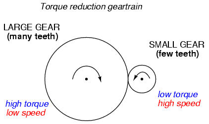
The step-up/step-down effect of coil turn ratios in a transformer is analogous to gear tooth ratios in mechanical gear systems, transforming values of speed and torque in much the same way:
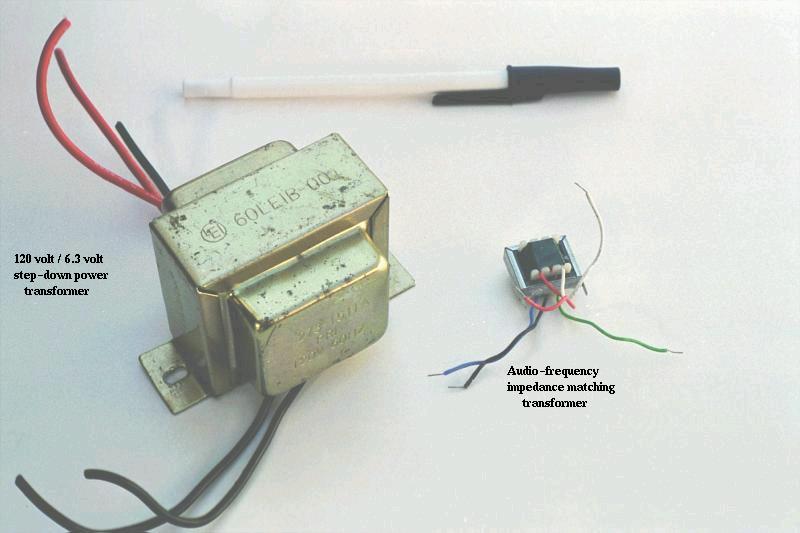
A small step-down power transformer used to convert 120 volt AC to 6.3 volt AC is shown on the left in the following photograph:
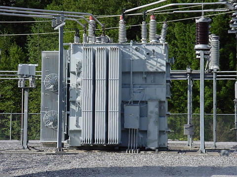
Step-up and step-down transformers for power distribution purposes can be gigantic in proportion to the small transformer shown above, some units standing as tall as a home. The following photograph shows a substation transformer standing about twelve feet tall:
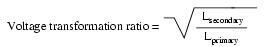
Aside from the ability to easily convert between different levels of voltage and current in AC and DC circuits, transformers also provide an extremely useful feature called isolation, which is the ability to couple one circuit to another without the use of direct wire connections. We can demonstrate an application of this effect with another SPICE simulation: this time showing "ground" connections for the two circuits, imposing a high DC voltage between one circuit and ground through the use of an additional voltage source:
v1 1 0 ac 10 sin
rbogus1 1 2 1e-12
v2 5 0 dc 250
l1 2 0 10000
l2 3 5 100
k l1 l2 0.999
vi1 3 4 ac 0
rload 4 5 1k
.ac lin 1 60 60
.print ac v(2,0) i(v1)
.print ac v(3,5) i(vi1)
.end
DC voltages referenced to ground (node 0):
(1)    0.0000    (2)    0.0000    (3)  250.0000
(4)  250.0000    (5)  250.0000
AC voltages:
freq          v(2)        i(v1)
6.000E+01     1.000E+01   9.975E-05    Primary winding
freq          v(3,5)      i(vi1)
6.000E+01     9.962E-01   9.962E-04    Secondary winding
SPICE shows the 250 volts DC being impressed upon the secondary circuit elements with respect to ground, but as you can see there is no effect on the primary circuit (zero DC voltage) at nodes 1 and 2, and the transformation of AC power from primary to secondary circuits remains the same as before. The impressed voltage in this example is often called a common-mode voltage because it is seen at more than one point in the circuit with reference to the common point of ground. The transformer isolates the common-mode voltage so that it is not impressed upon the primary circuit at all, but rather isolated to the secondary side. For the record, it does not matter that the common-mode voltage is DC, either. It could be AC, even at a different frequency, and the transformer would isolate it from the primary circuit all the same.
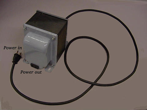
There are applications where electrical isolation is needed between two AC circuit without any transformation of voltage or current levels. In these instances, transformers called isolation transformers having 1:1 transformation ratios are used. A benchtop isolation transformer is shown in the following photograph:
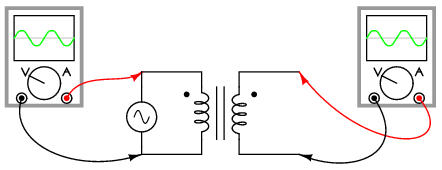
Since transformers are essentially AC devices, we need to be aware of the phase relationships between the primary and secondary circuits. Using our SPICE example from before, we can plot the waveshapes for the primary and secondary circuits and see the phase relations for ourselves:
legend:
*: v(2)     Primary voltage
+: v(3,5)   Secondary voltage
time       v(2)
(*)-----------     -10         -5          0          5         10
(+)-----------     -10         -5          0          5         10
- - - - - - - - - - - - - - - - - - - - - - - - - - - - - - - - -
0.000E+00  0.000E+00 .          .          x          .          .
1.000E-03  3.675E+00 .          .          .    + *   .          .
2.000E-03  6.803E+00 .          .          .          . + *      .
3.000E-03  9.008E+00 .          .          .          .      +*  .
4.000E-03  9.955E+00 .          .          .          .          x
5.000E-03  9.450E+00 .          .          .          .        *+.
6.000E-03  7.672E+00 .          .          .          .    * +   .
7.000E-03  4.804E+00 .          .          .         *.+         .
8.000E-03  1.245E+00 .          .          .  *  +    .          .
9.000E-03 -2.474E+00 .          .     * +  .          .          .
1.000E-02 -5.864E+00 .         *+          .          .          .
1.100E-02 -8.390E+00 .    *+    .          .          .          .
1.200E-02 -9.779E+00 .x         .          .          .          .
1.300E-02 -9.798E+00 +*         .          .          .          .
1.400E-02 -8.390E+00 .   +*     .          .          .          .
1.500E-02 -5.854E+00 .       + *.          .          .          .
1.600E-02 -2.479E+00 .          .    + *   .          .          .
1.700E-02  1.246E+00 .          .          .+ *       .          .
1.800E-02  4.795E+00 .          .          .       + *.          .
1.900E-02  7.686E+00 .          .          .          .   + *    .
2.000E-02  9.451E+00 .          .          .          .        x .
2.100E-02  9.937E+00 .          .          .          .          x
2.200E-02  9.025E+00 .          .          .          .       *+ .
2.300E-02  6.802E+00 .          .          .          .  *+      .
2.400E-02  3.667E+00 .          .          .      * + .          .
2.500E-02 -1.487E-03 .          .          * +        .          .
2.600E-02 -3.658E+00 .          .   * +    .          .          .
2.700E-02 -6.814E+00 .      * + .          .          .          .
2.800E-02 -9.026E+00 .  *+      .          .          .          .
2.900E-02 -9.917E+00 *+         .          .          .          .
3.000E-02 -9.511E+00 .x         .          .          .          .
- - - - - - - - - - - - - - - - - - - - - - - - - - - - - - - - -
legend:
*: i(v1)   Primary current
+: i(vi1)  Secondary current
time      i(v1)
(*)---------- -2.000E-04   -1.000E-04      0   1.000E-04  2.000E-04
(+)---------- -1.000E-03   -5.000E-04      0   5.000E-04  1.000E-03
- - - - - - - - - - - - - - - - - - - - - - - - - - - - - - - - -
0.000E+00  0.000E+00 .          .          x          .          .
1.000E-03 -2.973E-05 .          .     +   *.          .          .
2.000E-03 -6.279E-05 .        + .    *     .          .          .
3.000E-03 -8.772E-05 .   +      . *        .          .          .
4.000E-03 -1.008E-04 +          *          .          .          .
5.000E-03 -9.954E-05 .+         *          .          .          .
6.000E-03 -8.522E-05 .    +     . *        .          .          .
7.000E-03 -5.919E-05 .         +.     *    .          .          .
8.000E-03 -2.500E-05 .          .       + *.          .          .
9.000E-03  1.212E-05 .          .          . *  +     .          .
1.000E-02  4.736E-05 .          .          .     *    .+         .
1.100E-02  7.521E-05 .          .          .       *  .     +    .
1.200E-02  9.250E-05 .          .          .         *.         +.
1.300E-02  9.648E-05 .          .          .         *.          +
1.400E-02  8.602E-05 .          .          .        * .      +   .
1.500E-02  6.362E-05 .          .          .     *    . +        .
1.600E-02  3.177E-05 .          .          .  *  +    .          .
1.700E-02 -4.998E-06 .          .          x          .          .
1.800E-02 -4.136E-05 .          .  +    *  .          .          .
1.900E-02 -7.246E-05 .     +    .   *      .          .          .
2.000E-02 -9.331E-05 . +        .*         .          .          .
2.100E-02 -1.019E-04 +          *          .          .          .
2.200E-02 -9.651E-05 . +        *          .          .          .
2.300E-02 -7.749E-05 .     +    .  *       .          .          .
2.400E-02 -4.842E-05 .          . +    *   .          .          .
2.500E-02 -1.275E-05 .          .         x.          .          .
2.600E-02  2.428E-05 .          .          .  *  +    .          .
2.700E-02  5.761E-05 .          .          .     *    .+         .
2.800E-02  8.261E-05 .          .          .        * .       +  .
2.900E-02  9.514E-05 .          .          .         *.         +.
3.000E-02  9.487E-05 .          .          .         *.         +.
- - - - - - - - - - - - - - - - - - - - - - - - - - - - - - - - -
It would appear that both voltage and current for the two transformer windings are in phase with each other, at least for our resistive load. This is simple enough, but it would be nice to know which way we should connect a transformer in order to ensure the proper phase relationships be kept. After all, a transformer is nothing more than a set of magnetically-linked inductors, and inductors don't usually come with polarity markings of any kind. If we were to look at an unmarked transformer, we would have no way of knowing which way to hook it up to a circuit to get in-phase (or 180o out-of-phase) voltage and current:
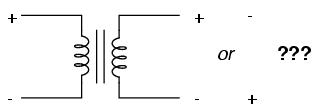
Since this is a practical concern, transformer manufacturers have come up with a sort of polarity marking standard to denote phase relationships. It is called the dot convention, and is nothing more than a dot placed next to each corresponding leg of a transformer winding:
Typically, the transformer will come with some kind of schematic diagram labeling the wire leads for primary and secondary windings. On the diagram will be a pair of dots similar to what is seen above. Sometimes dots will be omitted, but when "H" and "X" labels are used to label transformer winding wires, the subscript numbers are supposed to represent winding polarity. The "1" wires (H1 and X1) represent where the polarity-marking dots would normally be placed.
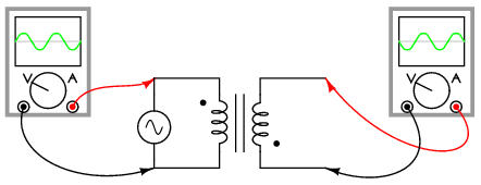
The similar placement of these dots next to the top ends of the primary and secondary windings tells us that whatever instantaneous voltage polarity seen across the primary winding will be the same as that across the secondary winding. In other words, the phase shift from primary to secondary will be zero degrees.
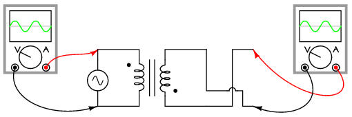
On the other hand, if the dots on each winding of the transformer do not match up, the phase shift will be 180o between primary and secondary, like this:
Of course, the dot convention only tells you which end of each winding is which, relative to the other winding(s). If you want to reverse the phase relationship yourself, all you have to do is swap the winding connections like this:
Transformers are very versatile devices. The basic concept of energy transfer between mutual inductors is useful enough between a single primary and single secondary coil, but transformers don't have to be made with just two sets of windings. Consider this transformer circuit:
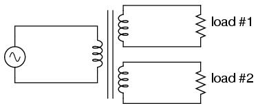
Here, three inductor coils share a common magnetic core, magnetically "coupling" or "linking" them together. The relationship of winding turn ratios and voltage ratios seen with a single pair of mutual inductors still holds true here for multiple pairs of coils. It is entirely possible to assemble a transformer such as the one above (one primary winding, two secondary windings) in which one secondary winding is a step-down and the other is a step-up. In fact, this design of transformer was quite common in vacuum tube power supply circuits, which were required to supply low voltage for the tubes' filaments (typically 6 or 12 volts) and high voltage for the tubes' plates (several hundred volts) from a nominal primary voltage of 110 volts AC. Not only are voltages and currents of completely different magnitudes possible with such a transformer, but all circuits are electrically isolated from one another.
A photograph of a multiple-winding transformer is shown here:
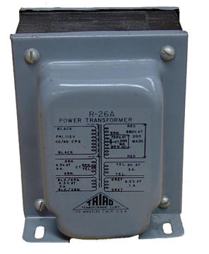
This particular transformer is intended to provide both high and low voltages necessary in an electronic system using vacuum tubes. Low voltage is required to power the filaments of vacuum tubes, while high voltage is required to create the potential difference between the plate and cathode elements of each tube. One transformer with multiple windings suffices elegantly to provide all the necessary voltage levels from a single 115 V source. The wires for this transformer (15 of them!) are not shown in the photograph, being hidden from view.
If electrical isolation between secondary circuits is not of great importance, a similar effect can be obtained by "tapping" a single secondary winding at multiple points along its length, like this:
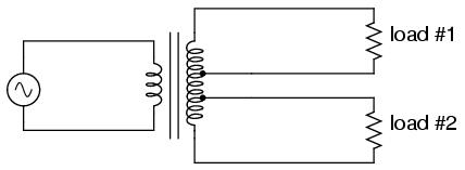
A tap is nothing more than a wire connection made at some point on a winding between the very ends. Not surprisingly, the winding turn/voltage magnitude relationship of a normal transformer holds true for all tapped segments of windings. This fact can be exploited to produce a transformer capable of multiple ratios:
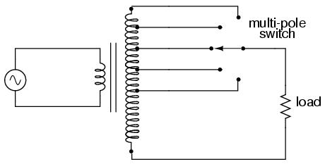
Carrying the concept of winding taps further, we end up with a "variable transformer," where a sliding contact is moved along the length of an exposed secondary winding, able to connect with it at any point along its length. The effect is equivalent to having a winding tap at every turn of the winding, and a switch with poles at every tap position:
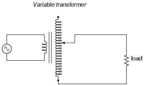
One consumer application of the variable transformer is in speed controls for model train sets, especially the train sets of the 1950's and 1960's. These transformers were essentially step-down units, the highest voltage obtainable from the secondary winding being substantially less than the primary voltage of 110 to 120 volts AC. The variable-sweep contact provided a simple means of voltage control with little wasted power, much more efficient than control using a variable resistor!
Moving-slide contacts are too impractical to be used in large industrial power transformer designs, but multi-pole switches and winding taps are common for voltage adjustment. Adjustments need to be made periodically in power systems to accommodate changes in loads over months or years in time, and these switching circuits provide a convenient means. Typically, such "tap switches" are not engineered to handle full-load current, but must be actuated only when the transformer has been de-energized (no power).
Seeing as how we can tap any transformer winding to obtain the equivalent of several windings (albeit with loss of electrical isolation between them), it makes sense that it should be possible to forego electrical isolation altogether and build a transformer from a single winding. Indeed this is possible, and the resulting device is called an autotransformer:
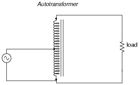
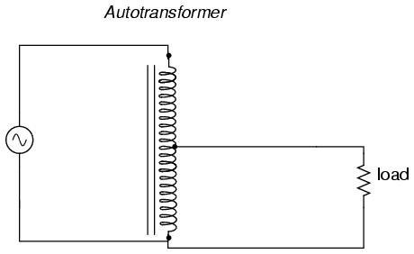
The autotransformer depicted above performs a voltage step-up function. A step-down autotransformer would look something like this:
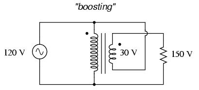
Autotransformers find popular use in applications requiring a slight boost or reduction in voltage to a load. The alternative with a normal (isolated) transformer would be to either have just the right primary/secondary winding ratio made for the job or use a step-down configuration with the secondary winding connected in series-aiding ("boosting") or series-opposing ("bucking") fashion. Primary, secondary, and load voltages are given to illustrate how this would work.
First, the "boosting" configuration. Here, the secondary coil's polarity is oriented so that its voltage directly adds to the primary voltage:
Next, the "bucking" configuration. Here, the secondary coil's polarity is oriented so that its voltage directly subtracts from the primary voltage:
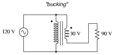
The prime advantage of an autotransformer is that the same boosting or bucking function is obtained with only a single winding, making it cheaper and lighter to manufacture than a regular (isolating) transformer having both primary and secondary windings.
Like regular transformers, autotransformer windings can be tapped to provide variations in ratio. Additionally, they can be made continuously variable with a sliding contact to tap the winding at any point along its length. The latter configuration is popular enough to have earned itself its own name: the Variac.
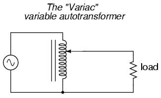
Small variacs for benchtop use are popular pieces of equipment for the electronics experimenter, being able to step household AC voltage down (or sometimes up as well) with a wide, fine range of control by a simple twist of a knob.
As we saw in a few SPICE analyses earlier in this chapter, the output voltage of a transformer varies some with varying load resistances, even with a constant voltage input. The degree of variance is affected by the primary and secondary winding inductances, among other factors, not the least of which includes winding resistance and the degree of mutual inductance (magnetic coupling) between the primary and secondary windings. For power transformer applications, where the transformer is seen by the load (ideally) as a constant source of voltage, it is good to have the secondary voltage vary as little as possible for wide variances in load current.
The measure of how well a power transformer maintains constant secondary voltage over a range of load currents is called the transformer's voltage regulation. It can be calculated from the following formula:
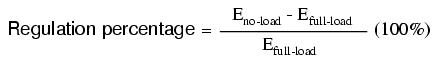
"Full-load" means the point at which the transformer is operating at maximum permissible secondary current. This operating point will be determined primarily by the winding wire size (ampacity) and the method of transformer cooling. Taking our first SPICE transformer simulation as an example, let's compare the output voltage with a 1 kΩ load versus a 200 Ω load (assuming that the 200 Ω load will be our "full load" condition). Recall if you will that our constant primary voltage was 10.00 volts AC:
freq          v(3,5)      i(vi1)
6.000E+01     9.962E+00   9.962E-03    Output with 1k ohm load
freq          v(3,5)      i(vi1)
6.000E+01     9.348E+00   4.674E-02    Output with 200 ohm load
Notice how the output voltage decreases as the load gets heavier (more current). Now let's take that same transformer circuit and place a load resistance of extremely high magnitude across the secondary winding to simulate a "no-load" condition:
transformer
v1 1 0 ac 10 sin
rbogus1 1 2 1e-12
rbogus2 5 0 9e12
l1 2 0 100
l2 3 5 100
k l1 l2 0.999
vi1 3 4 ac 0
rload 4 5 9e12
.ac lin 1 60 60
.print ac v(2,0) i(v1)
.print ac v(3,5) i(vi1)
.end
freq          v(2)        i(v1)
6.000E+01     1.000E+01   2.653E-04
freq          v(3,5)      i(vi1)
6.000E+01     9.990E+00   1.110E-12   Output with (almost) no load
So, we see that our output (secondary) voltage spans a range of 9.990 volts at (virtually) no load and 9.348 volts at the point we decided to call "full load." Calculating voltage regulation with these figures, we get:
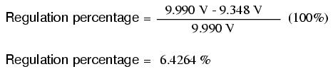
Incidentally, this would be considered rather poor (or "loose") regulation for a power transformer. Powering a simple resistive load like this, a good power transformer should exhibit a regulation percentage of less than 3%. Inductive loads tend to create a condition of worse voltage regulation, so this analysis with purely resistive loads was a "best-case" condition.
There are some applications, however, where poor regulation is actually desired. One such case is in discharge lighting, where a step-up transformer is required to initially generate a high voltage (necessary to "ignite" the lamps), then the voltage is expected to drop off once the lamp begins to draw current. This is because discharge lamps' voltage requirements tend to be much lower after a current has been established through the arc path. In this case, a step-up transformer with poor voltage regulation suffices nicely for the task of conditioning power to the lamp.
Another application is in current control for AC arc welders, which are nothing more than step-down transformers supplying low-voltage, high-current power for the welding process. A high voltage is desired to assist in "striking" the arc (getting it started), but like the discharge lamp, an arc doesn't require as much voltage to sustain itself once the air has been heated to the point of ionization. Thus, a decrease of secondary voltage under high load current would be a good thing. Some arc welder designs provide arc current adjustment by means of a movable iron core in the transformer, cranked in or out of the winding assembly by the operator. Moving the iron slug away from the windings reduces the strength of magnetic coupling between the windings, which diminishes no-load secondary voltage and makes for poorer voltage regulation.
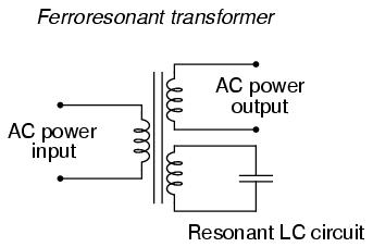
No exposition on transformer regulation could be called complete without mention of an unusual device called a ferroresonant transformer. "Ferroresonance" is a phenomenon associated with the behavior of iron cores while operating near a point of magnetic saturation (where the core is so strongly magnetized that further increases in winding current results in little or no increase in magnetic flux).
While being somewhat difficult to describe without going deep into electromagnetic theory, the ferroresonant transformer is a power transformer engineered to operate in a condition of persistent core saturation. That is, its iron core is "stuffed full" of magnetic lines of flux for a large portion of the AC cycle so that variations in supply voltage (primary winding current) have little effect on the magnetic field strength in the core, which means the secondary winding outputs a nearly constant voltage despite significant variations in supply (primary winding) voltage. Normally, core saturation in a transformer results in distortion of the sinewave shape, and the ferroresonant transformer is no exception. To combat this side effect, ferroresonant transformers have an auxiliary secondary winding paralleled with one or more capacitors, forming a resonant circuit tuned to the power supply frequency. This "tank circuit" serves as a filter to reject harmonics created by the core saturation, and provides the added benefit of storing energy in the form of AC oscillations, which is available for sustaining output winding voltage for brief periods of input voltage loss (milliseconds' worth of time, but certainly better than nothing).
In addition to blocking harmonics created by the saturated core, this resonant circuit also "filters out" harmonic frequencies generated by nonlinear (switching) loads in the secondary winding circuit and any harmonics present in the source voltage, providing "clean" power to the load.
Ferroresonant transformers offer several features useful in AC power conditioning: constant output voltage given substantial variations in input voltage, harmonic filtering between the power source and the load, and the ability to "ride through" brief losses in power by keeping a reserve of energy in its resonant tank circuit. These transformers are also highly tolerant of excessive loading and transient (momentary) voltage surges. They are so tolerant, in fact, that some may be briefly paralleled with unsynchronized AC power sources, allowing a load to be switched from one source of power to another in a "make-before-break" fashion with no interruption of power on the secondary side!
Unfortunately, these devices have equally noteworthy disadvantages: they waste a lot of energy (due to hysteresis losses in the saturated core), generating significant heat in the process, and are intolerant of frequency variations, which means they don't work very well when powered by small engine-driven generators having poor speed regulation. Voltages produced in the resonant winding/capacitor circuit tend to be very high, necessitating expensive capacitors and presenting the service technician with very dangerous working voltages. Some applications, though, may prioritize the ferroresonant transformer's advantages over its disadvantages. Semiconductor circuits exist to "condition" AC power as an alternative to ferroresonant devices, but none can compete with this transformer in terms of sheer simplicity.
Because transformers can step voltage and current to different levels, and because power is transferred equivalently between primary and secondary windings, they can be used to "convert" the impedance of a load to a different level. That last phrase deserves some explanation, so let's investigate what it means.
The purpose of a load (usually) is to do something productive with the power it dissipates. In the case of a resistive heating element, the practical purpose for the power dissipated is to heat something up. Loads are engineered to safely dissipate a certain maximum amount of power, but two loads of equal power rating are not necessarily identical. Consider these two 1000 watt resistive heating elements:
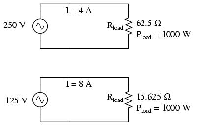
Both heaters dissipate exactly 1000 watts of power, but they do so at different voltage and current levels (either 250 volts and 4 amps, or 125 volts and 8 amps). Using Ohm's Law to determine the necessary resistance of these heating elements (R=E/I), we arrive at figures of 62.5 Ω and 15.625 Ω, respectively. If these are AC loads, we might refer to their opposition to current in terms of impedance rather than plain resistance, although in this case that's all they're composed of (no reactance). The 250 volt heater would be said to be a higher impedance load than the 125 volt heater.
If we desired to operate the 250 volt heater element directly on a 125 volt power system, we would end up being disappointed. With 62.5 Ω of impedance (resistance), the current would only be 2 amps (I=E/R; 125/62.5), and the power dissipation would only be 250 watts (P=IE; 125 x 2), or one-quarter of its rated power. The impedance of the heater and the voltage of our source would be mismatched, and we couldn't obtain the full rated power dissipation from the heater.
All hope is not lost, though. With a step-up transformer, we could operate the 250 volt heater element on the 125 volt power system like this:

The ratio of the transformer's windings provides the voltage step-up and current step-down we need for the otherwise mismatched load to operate properly on this system. Take a close look at the primary circuit figures: 125 volts at 8 amps. As far as the power supply "knows," it's powering a 15.625 Ω (R=E/I) load at 125 volts, not a 62.5 Ω load! The voltage and current figures for the primary winding are indicative of 15.625 Ω load impedance, not the actual 62.5 Ω of the load itself. In other words, not only has our step-up transformer transformed voltage and current, but it has transformed impedance as well.
The transformation ratio of impedance is the square of the voltage/current transformation ratio, the same as the winding inductance ratio:
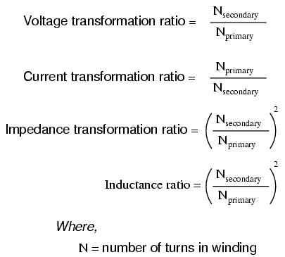
This concurs with our example of the 2:1 step-up transformer and the impedance ratio of 62.5 Ω to 15.625 Ω (a 4:1 ratio, which is 2:1 squared). Impedance transformation is a highly useful ability of transformers, for it allows a load to dissipate its full rated power even if the power system is not at the proper voltage to directly do so.
Recall from our study of network analysis the Maximum Power Transfer Theorem, which states that the maximum amount of power will be dissipated by a load resistance when that load resistance is equal to the Thevenin/Norton resistance of the network supplying the power. Substitute the word "impedance" for "resistance" in that definition and you have the AC version of that Theorem. If we're trying to obtain theoretical maximum power dissipation from a load, we must be able to properly match the load impedance and source (Thevenin/Norton) impedance together. This is generally more of a concern in specialized electric circuits such as radio transmitter/antenna and audio amplifier/speaker systems. Let's take an audio amplifier system and see how it works:
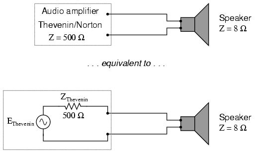
With an internal impedance of 500 Ω, the amplifier can only deliver full power to a load (speaker) also having 500 Ω of impedance. Such a load would drop higher voltage and draw less current than an 8 Ω speaker dissipating the same amount of power. If an 8 Ω speaker were connected directly to the 500 Ω amplifier as shown, the impedance mismatch would result in very poor (low peak power) performance. Additionally, the amplifier would tend to dissipate more than its fair share of power in the form of heat trying to drive the low impedance speaker.
To make this system work better, we can use a transformer to match these mismatched impedances. Since we're going from a high impedance (high voltage, low current) supply to a low impedance (low voltage, high current) load, we'll need to use a step-down transformer:
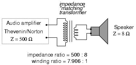
To obtain an impedance transformation ratio of 500:8, we would need a winding ratio equal to the square root of 500:8 (the square root of 62.5:1, or 7.906:1). With such a transformer in place, the speaker will load the amplifier to just the right degree, drawing power at the correct voltage and current levels to satisfy the Maximum Power Transfer Theorem and make for the most efficient power delivery to the load. The use of a transformer in this capacity is called impedance matching.
Anyone who has ridden a multi-speed bicycle can intuitively understand the principle of impedance matching. A human's legs will produce maximum power when spinning the bicycle crank at a particular speed (about 60 to 90 revolution per minute). Above or below that rotational speed, human leg muscles are less efficient at generating power. The purpose of the bicycle's "gears" is to impedance-match the rider's legs to the riding conditions so that they always spin the crank at the optimum speed.
If the rider attempts to start moving while the bicycle is shifted into its "top" gear, he or she will find it very difficult to get moving. Is it because the rider is weak? No, it's because the high step-up ratio of the bicycle's chain and sprockets in that top gear presents a mismatch between the conditions (lots of inertia to overcome) and their legs (needing to spin at 60-90 RPM for maximum power output). On the other hand, selecting a gear that is too low will enable the rider to get moving immediately, but limit the top speed they will be able to attain. Again, is the lack of speed an indication of weakness in the bicyclist's legs? No, it's because the lower speed ratio of the selected gear creates another type of mismatch between the conditions (low load) and the rider's legs (losing power if spinning faster than 90 RPM). It is much the same with electric power sources and loads: there must be an impedance match for maximum system efficiency. In AC circuits, transformers perform the same matching function as the sprockets and chain ("gears") on a bicycle to match otherwise mismatched sources and loads.
Impedance matching transformers are not fundamentally different from any other type of transformer in construction or appearance. A small impedance-matching transformer for audio-frequency applications is shown on the right in the following photograph:
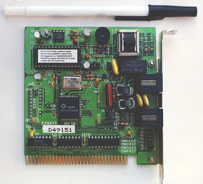
Another impedance-matching transformer can be seen on this printed circuit board, in the upper right corner, to the immediate left of resistors R2 and R1. It is labeled "T1":
Transformers can also be used in electrical instrumentation systems. Due to transformers' ability to step up or step down voltage and current, and the electrical isolation they provide, they can serve as a way of connecting electrical instrumentation to high-voltage, high current power systems. Suppose we wanted to accurately measure the voltage of a 13.8 kV power system (a very common high voltage standard in industry):
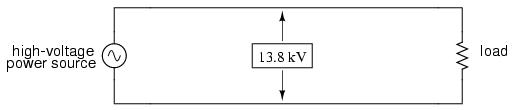
Designing, installing, and maintaining a voltmeter capable of directly measuring 13,800 volts AC would be no easy task. The safety hazard alone of bringing 13.8 kV conductors into the back of an instrument panel would be severe. However, by using a precision step-down transformer, we can reduce the 13.8 kV down to a safe level of voltage at a constant ratio, and isolate it from the instrument connections, adding an additional level of safety to the metering system:
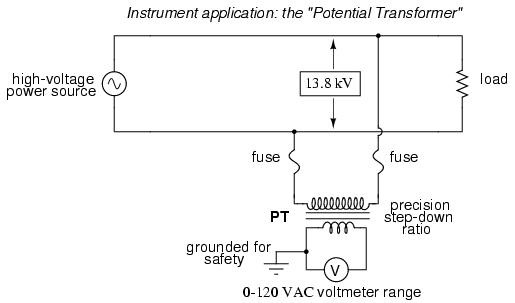
Now the voltmeter reads a precise fraction, or ratio, of the actual system voltage, its scale set to read as though it were measuring the voltage directly. The transformer keeps the instrument voltage at a safe level and electrically isolates it from the power system, so there is no direct connection between the power lines and the instrument or instrument wiring. When used in this capacity, the transformer is called a Potential Transformer, or simply PT.
Potential transformers are designed to provide as accurate a voltage step-down ratio as possible. To aid in precise voltage regulation, loading is kept to a minimum: the voltmeter is made to have high input impedance so as to draw as little current from the PT as possible. As you can see, a fuse has been connected in series with the PTs primary winding, for safety and ease of disconnecting the PT from the circuit.
A standard secondary voltage for a PT is 120 volts AC, for full-rated power line voltage. The standard voltmeter range to accompany a PT is 150 volts, full-scale. PTs with custom winding ratios can be manufactured to suit any application. This lends itself well to industry standardization of the actual voltmeter instruments themselves, since the PT will be sized to step the system voltage down to this standard instrument level.
Following the same line of thinking, we can use a transformer to step down current through a power line so that we are able to safely and easily measure high system currents with inexpensive ammeters. Of course, such a transformer would be connected in series with the power line, like this:
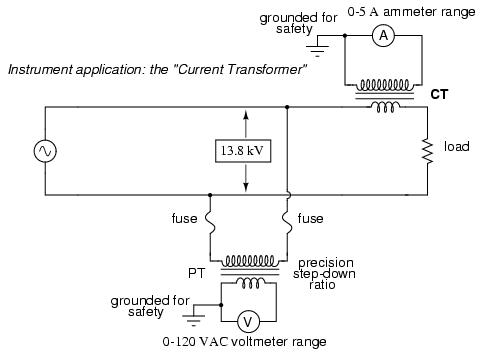
Note that while the PT is a step-down device, the Current Transformer (or CT) is a step-up device (with respect to voltage), which is what is needed to step down the power line current. Quite often, CTs are built as donut-shaped devices through which the power line conductor is run, the power line itself acting as a single-turn primary winding:
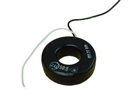
Some CTs are made to hinge open, allowing insertion around a power conductor without disturbing the conductor at all. The industry standard secondary current for a CT is a range of 0 to 5 amps AC. Like PTs, CTs can be made with custom winding ratios to fit almost any application. Because their "full load" secondary current is 5 amps, CT ratios are usually described in terms of full-load primary amps to 5 amps, like this:
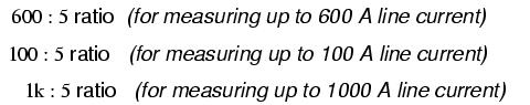
The "donut" CT shown in the photograph has a ratio of 50:5. That is, when the conductor through the center of the torus is carrying 50 amps of current (AC), there will be 5 amps of current induced in the CT's winding.
Because CTs are designed to be powering ammeters, which are low-impedance loads, and they are wound as voltage step-up transformers, they should never, ever be operated with an open-circuited secondary winding. Failure to heed this warning will result in the CT producing extremely high secondary voltages, dangerous to equipment and personnel alike. To facilitate maintenance of ammeter instrumentation, short-circuiting switches are often installed in parallel with the CT's secondary winding, to be closed whenever the ammeter is removed for service:
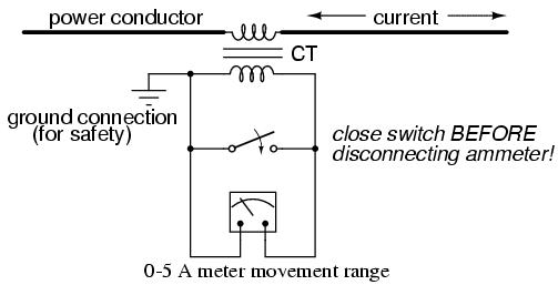
Though it may seem strange to intentionally short-circuit a power system component, it is perfectly proper and quite necessary when working with current transformers.
Another kind of special transformer, seen often in radio-frequency circuits, is the air core transformer. True to its name, an air core transformer has its windings wrapped around a nonmagnetic form, usually a hollow tube of some material. The degree of coupling (mutual inductance) between windings in such a transformer is many times less than that of an equivalent iron-core transformer, but the undesirable characteristics of a ferromagnetic core (eddy current losses, hysteresis, saturation, etc.) are completely eliminated. It is in high-frequency applications that these effects of iron cores are most problematic.
One notable example of air-core transformer is the Tesla Coil, named after the Serbian electrical genius Nikola Tesla, who was also the inventor of the rotating magnetic field AC motor, polyphase AC power systems, and many elements of radio technology. The Tesla Coil is a resonant, high-frequency step-up transformer used to produce high voltages that are relatively harmless to human beings (the "skin effect" of high-frequency alternating current precluding electric shock, although capable of producing skin burns). One of Tesla's dreams was to employ his coil technology to distribute electric power without the need for wires, simply broadcasting it in the form of radio waves which could be received and conducted to loads by means of antennas. The basic schematic for a Tesla Coil looks like this:
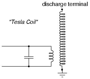
The capacitor in parallel with the transformer's primary winding forms the tank circuit needed for resonance. The secondary winding is wound in close proximity to the primary, usually around the same nonmagnetic form. Several options exist for "exciting" the primary circuit, the simplest being a high-voltage, low-frequency AC source and spark gap:
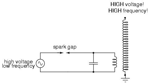
With each cycle peak of the high-voltage AC source, the current will jump across the spark gap, briefly energizing the tank circuit. The tank circuit, tuned for a resonant frequency far in excess of the AC source, will oscillate for many cycles before the next cycle peak of the source, when it will receive another "kick" to keep the oscillations going. The secondary of the Tesla Coil will output a fairly constant high voltage at very high frequencies, usually producing a spark discharge into the surrounding air at the discharge terminal.
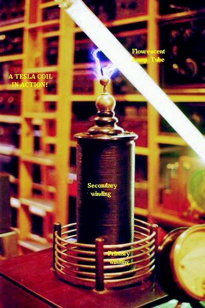
Tesla Coils find application primarily as novelty devices, showing up in high school science fairs, basement workshops, and the occasional low budget science-fiction movie.
So far, we've explored the transformer as a device for converting different levels of voltage, current, and even impedance from one circuit to another. Now we'll take a look at it as a completely different kind of device: one that allows a small electrical signal to exert control over a much larger quantity of electrical power. In this mode, a transformer acts as an amplifier.
The device I'm referring to is called a saturable-core reactor, or simply saturable reactor. Actually, it is not really a transformer at all, but rather a special kind of inductor whose inductance can be varied by the application of a DC current through a second winding wound around the same iron core. Like the ferroresonant transformer, the saturable reactor relies on the principle of magnetic saturation. When a material such as iron is completely saturated (that is, all its magnetic domains are lined up with the applied magnetizing force), additional increases in current through the magnetizing winding will not result in further increases of magnetic flux.
Now, inductance is the measure of how well an inductor opposes changes in current by developing a voltage in an opposing direction. The ability of an inductor to generate this opposing voltage is directly connected with the change in magnetic flux inside the inductor resulting from the change in current, and the number of winding turns in the inductor. If an inductor has a saturated core, no further magnetic flux will result from further increases in current, and so there will be no voltage induced in opposition to the change in current. In other words, an inductor loses its inductance (ability to oppose changes in current) when its core becomes magnetically saturated.
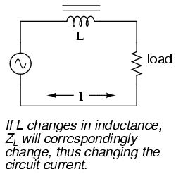
If an inductor's inductance changes, then its reactance (and impedance) to AC current changes as well. In a circuit with a constant voltage source, this will result in a change in current:
A saturable reactor capitalizes on this effect by forcing the ferromagnetic core into a state of saturation with a strong magnetic field generated by current through another winding. The reactor's "power" winding is the one carrying the AC load current, and the "control" winding is one carrying a DC current strong enough to drive the core into saturation:
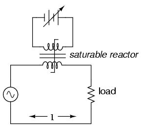
The strange-looking transformer symbol shown in the above schematic represents a saturable-core reactor, the upper winding being the DC control winding and the lower being the "power" winding through which the controlled AC current goes. Increased DC control current produces more magnetic flux in the reactor core, driving it closer to a condition of saturation, thus decreasing the power winding's inductance, decreasing its impedance, and increasing current to the load. Thus, the DC control current is able to exert control over the AC current delivered to the load.
The circuit shown would work, but it would not work very well. The first problem is the natural transformer action of the saturable reactor: AC current through the power winding will try to induce current in the control winding, which may cause trouble in the DC power source. Also, saturable reactors tend to regulate AC power only in one direction: in one half of the AC cycle, the magnetic field forces from both windings add; in the other half, they subtract. Thus, the core will tend to be more saturated in one half of the AC cycle than the other, passing current more easily in one direction than the other. Fortunately, both problems can be overcome with a little ingenuity:
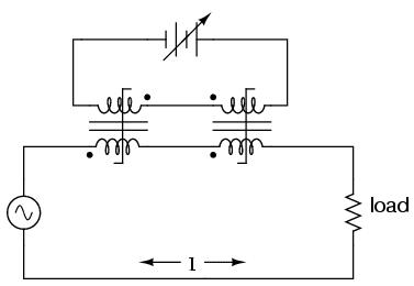
Notice the placement of the phasing dots on the two reactors: the power windings are "in phase" while the control windings are "out of phase." If both reactors are identical, any voltage induced in the control windings by load current through the power windings will cancel out to zero at the battery terminals, thus eliminating the first problem mentioned. Furthermore, since the DC control current through both reactors produces magnetic fields in different directions through the reactor cores, one reactor will saturate more in one cycle of the AC power while the other reactor will saturate more in the other, thus equalizing the control action through each half-cycle so that the AC power is "throttled" symmetrically. This phasing of control windings can be accomplished with two separate reactors as shown, or in a single reactor design with intelligent layout of the windings and core.
Saturable reactor technology has even been miniaturized to the circuit-board level in compact packages more generally known as magnetic amplifiers. I personally find this to be fascinating: the effect of amplification (one electrical signal controlling another), normally requiring the use of physically fragile vacuum tubes or electrically "fragile" semiconductor devices, can be realized in a device both physically and electrically rugged. Magnetic amplifiers do have disadvantages over their more fragile counterparts, namely size, weight, nonlinearity, and bandwidth (frequency response), but their utter simplicity still commands a certain degree of appreciation, if not practical application.
Saturable-core reactors are less commonly known as "saturable-core inductors" or transductors.
As has already been observed, transformers must be designed for specific purposes in order to achieve good power coupling and required voltage regulation. There is no "one size fits all" transformer design, and never will be. In addition to winding inductance and magnetic coupling parameters, a real transformer must be designed to carry the expected values of current without any trouble. This means the winding conductors must be made of the proper gage wire to avoid any heating problems. Here is yet another design parameter that makes a "one size fits all" ideal transformer impossible to construct.
Additionally, winding conductor insulation is a concern where high voltages are encountered, as they often are in step-up and step-down power distribution transformers. Not only do the windings have to be well insulated from the iron core, but each winding has to be sufficiently insulated from the other in order to maintain electrical isolation between windings.
Beyond the concern of winding conductor ampacity and insulation voltage ratings, we have the magnetic flux limitations of the core. For ferromagnetic core transformers, we must be mindful of the saturation limits of the core. Remember that ferromagnetic materials cannot support infinite magnetic flux densities: they tend to "saturate" at a certain level (dictated by the material and core dimensions), meaning that further increases in magnetic field force do not result in proportional increases in magnetic field flux. Normally, transformer designers rate the cores conservatively so as to avoid approaching these limits.
If a transformer's primary winding is overloaded (too much current), there may be excessive levels of magnetic field force imposed on the core at peak moments of the AC sinewave cycle, driving it to saturation. When this happens, the voltage induced in the secondary winding will no longer match the wave-shape as the voltage powering the primary coil. In other words, the overloaded transformer will distort the waveshape from primary to secondary windings, creating harmonics in the secondary winding's output. As we discussed before, harmonic content in AC power systems typically causes problems.
Respecting these limitations, transformers are rated for certain levels of primary and secondary winding voltage and current, though the current rating is usually derived from a volt-amp (VA) rating assigned to the transformer. For example, take a step-down transformer with a primary voltage rating of 120 volts, a secondary voltage rating of 48 volts, and a VA rating of 1 kVA (1000 VA). The maximum winding currents can be determined as such:
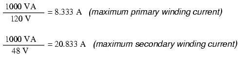
Sometimes windings will bear current ratings in amps, but this is typically seen on small transformers. Large transformers are almost always rated in terms of winding voltage and VA or kVA.
When transformers transfer power, they do so with a minimum of loss. As it was stated earlier, modern power transformer designs typically exceed 95% efficiency. It is good to know where some of this lost power goes, however, and what causes it to be lost.
There is, of course, power lost due to resistance of the wire windings. Unless superconducting wires are used, there will always be power dissipated in the form of heat through the resistance of current-carrying conductors. Because transformers require such long lengths of wire, this loss can be a significant factor. Increasing the gage of the winding wire is one way to minimize this loss, but only with substantial increases in cost, size, and weight.
Resistive losses aside, the bulk of transformer power loss is due to magnetic effects in the core. Perhaps the most significant of these "core losses" is eddy-current loss, which is resistive power dissipation due to the passage of induced currents through the iron of the core. Because iron is a conductor of electricity as well as being an excellent "conductor" of magnetic flux, there will be currents induced in the iron just as there are currents induced in the secondary windings from the alternating magnetic field. These induced currents -- following the perpendicularity clause of Faraday's Law of Electromagnetic Induction -- tend to circulate through the cross-section of the core perpendicularly to the primary winding turns. Their circular motion gives them their unusual name: like eddies in a stream of water that circulate rather than move in straight lines.
Iron is a fair conductor of electricity, but not as good as the copper or aluminum from which wire windings are typically made. Consequently, these "eddy currents" must overcome significant electrical resistance as they circulate through the core. In overcoming the resistance offered by the iron, they dissipate power in the form of heat. Hence, we have a source of inefficiency in the transformer that is difficult to eliminate. The main strategy in mitigating these wasteful eddy currents is to form the iron core in many thin sheets, each sheet covered with an insulating varnish so that the core is divided up into skinny slices. The result is very little width in the core for eddy currents to circulate in:
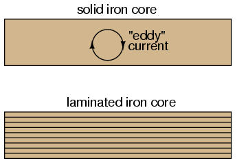
Laminated cores like the one shown here are standard in almost all low-frequency transformers. Another, similar technique for minimizing eddy current losses which works better for high-frequency applications is to make the core out of iron powder instead of thin iron sheets. Like the lamination sheets, these granules of iron are individually coated in an electrically insulating material, which makes the core nonconductive except for within the width of each granule. Powdered iron cores are often found in transformers handling radio-frequency currents.
Another "core loss" is that of magnetic hysteresis. All ferromagnetic materials tend to retain some degree of magnetization after exposure to an external magnetic field. This tendency to stay magnetized is called "hysteresis," and it takes a certain investment in energy to overcome this opposition to change every time the magnetic field produced by the primary winding changes polarity (twice per AC cycle). This type of loss can be mitigated through good core material selection, choosing a core alloy with low hysteresis.
Transformer energy losses tend to get worse with increasing frequency. The skin effect within winding conductors reduces the available cross-sectional area for electron flow, thereby increasing effective resistance as the frequency goes up and creating more power lost through resistive dissipation. Magnetic core losses are also exaggerated with higher frequencies, eddy currents and hysteresis effects becoming more severe. For this reason, transformers of significant size are designed to operate efficiently in a limited range of frequencies. In most power distribution systems where the line frequency is very stable, one would think excessive frequency would never pose a problem. Unfortunately it does, in the form of harmonics created by nonlinear loads.
As we've seen in earlier chapters, nonsinusoidal waveforms are equivalent to additive series of multiple sinusoidal waveforms at different amplitudes and frequencies. In power systems, these other frequencies are whole-number multiples of the fundamental (line) frequency, meaning that they will always be higher, not lower, than the design frequency of the transformer. In significant measure, they can cause severe transformer overheating. Power transformers can be engineered to handle certain levels of power system harmonics, and this capability is sometimes denoted with a "K factor" rating.
Aside from power ratings and power losses, transformers often harbor other undesirable limitations which circuit designers must be made aware of. Like their simpler counterparts -- inductors -- transformers exhibit capacitance due to the insulation dielectric between conductors: from winding to winding, turn to turn (in a single winding), and winding to core. Usually this capacitance is of no concern in a power application, but small signal applications (especially those of high frequency) may not tolerate this quirk well. Also, the effect of having capacitance along with the windings' designed inductance gives transformers the ability to resonate at a particular frequency, definitely a design concern in signal applications where the applied frequency may reach this point (usually the resonant frequency of a power transformer is well beyond the frequency of the AC power it was designed to operate on).
Flux containment (making sure a transformer's magnetic flux doesn't escape so as to interfere with another device, and making sure other devices' magnetic flux is shielded from the transformer core) is another concern shared both by inductors and transformers.
Transformers do have some unique concerns, though, due to the priority of mutual inductance between primary and secondary windings. In many applications it is desirable to have 100% coupling between windings, so that the transformer is able to cleanly transfer power between windings without acting like an inductor. However, any magnetic flux not coupled between windings in a transformer is free to simply store and release energy (rather than transfer it from one coil to another). Any energy thusly stored and released by this uncoupled flux manifests itself as an inductance in series with the producing winding. This stray inductance is called leakage inductance.
Leakage inductance has a detrimental effect on voltage regulation. Because leakage inductance is equivalent to an inductance connected in series with the transformer's winding, it manifests itself as a series impedance with the load. Thus, the more current drawn by the load, the less voltage available at the secondary winding terminals. Usually, good voltage regulation is desired in transformer design, but there are exceptional applications. As was stated before, discharge lighting circuits require a step-up transformer with "loose" (poor) voltage regulation to ensure reduced voltage after the establishment of an arc through the lamp. One way to meet this design criterion is to engineer the transformer with flux leakage paths for magnetic flux to bypass the secondary winding(s). The resulting leakage flux will produce leakage inductance, which will in turn produce the poor regulation needed for discharge lighting.
In addition to unwanted electrical effects, transformers also exhibit some undesirable physical effects, the most notable being the production of heat and noise. Heating may be minimized by good design, ensuring that the core does not approach saturation levels, that eddy currents are minimized, and that the windings are not overloaded or operated too close to maximum ampacity. Noise, on the other hand, is an effect originating from the phenomenon of magnetostriction: the change of length exhibited by a ferromagnetic object when magnetized. The familiar "hum" heard around large power transformers is the sound of the iron core expanding and contracting at 120 Hz (twice the system frequency, which is 60 Hz in the United States), once for every peak of the current (magnetic flux) waveform. Again, maintaining low magnetic flux levels in the core is the key to minimizing this effect, which explains why ferroresonant transformers -- which must operate in saturation for a large portion of the current waveform -- operate both hot and noisy.