


In the design of large and complex digital systems, it is often necessary to have one device communicate digital information to and from other devices. One advantage of digital information is that it tends to be far more resistant to transmitted and interpreted errors than information symbolized in an analog medium. This accounts for the clarity of digitally-encoded telephone connections, compact audio disks, and for much of the enthusiasm in the engineering community for digital communications technology. However, digital communication has its own unique pitfalls, and there are multitudes of different and incompatible ways in which it can be sent. Hopefully, this chapter will enlighten you as to the basics of digital communication, its advantages, disadvantages, and practical considerations.
Suppose we are given the task of remotely monitoring the level of a water storage tank. Our job is to design a system to measure the level of water in the tank and send this information to a distant location so that other people may monitor it. Measuring the tank's level is quite easy, and can be accomplished with a number of different types of instruments, such as float switches, pressure transmitters, ultrasonic level detectors, capacitance probes, strain gauges, or radar level detectors.
For the sake of this illustration, we will use an analog level-measuring device with an output signal of 4-20 mA. 4 mA represents a tank level of 0%, 20 mA represents a tank level of 100%, and anything in between 4 and 20 mA represents a tank level proportionately between 0% and 100%. If we wanted to, we could simply send this 4-20 milliamp analog current signal to the remote monitoring location by means of a pair of copper wires, where it would drive a panel meter of some sort, the scale of which was calibrated to reflect the depth of water in the tank, in whatever units of measurement preferred.
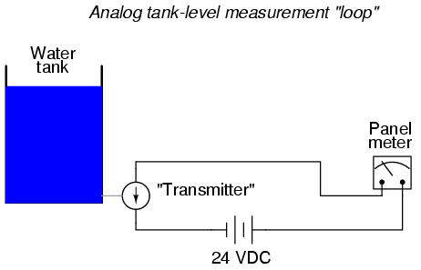
This analog communication system would be simple and robust. For many applications, it would suffice for our needs perfectly. But, it is not the only way to get the job done. For the purposes of exploring digital techniques, we'll explore other methods of monitoring this hypothetical tank, even though the analog method just described might be the most practical.
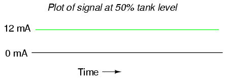
The analog system, as simple as it may be, does have its limitations. One of them is the problem of analog signal interference. Since the tank's water level is symbolized by the magnitude of DC current in the circuit, any "noise" in this signal will be interpreted as a change in the water level. With no noise, a plot of the current signal over time for a steady tank level of 50% would look like this:
If the wires of this circuit are arranged too close to wires carrying 60 Hz AC power, for example, inductive and capacitive coupling may create a false "noise" signal to be introduced into this otherwise DC circuit. Although the low impedance of a 4-20 mA loop (250 Ω, typically) means that small noise voltages are significantly loaded (and thereby attenuated by the inefficiency of the capacitive/inductive coupling formed by the power wires), such noise can be significant enough to cause measurement problems:
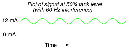
The above example is a bit exaggerated, but the concept should be clear: any electrical noise introduced into an analog measurement system will be interpreted as changes in the measured quantity. One way to combat this problem is to symbolize the tank's water level by means of a digital signal instead of an analog signal. We can do this really crudely by replacing the analog transmitter device with a set of water level switches mounted at different heights on the tank:
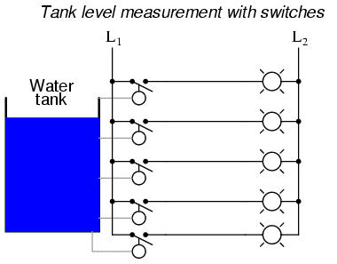
Each of these switches is wired to close a circuit, sending current to individual lamps mounted on a panel at the monitoring location. As each switch closed, its respective lamp would light, and whoever looked at the panel would see a 5-lamp representation of the tank's level.
Being that each lamp circuit is digital in nature -- either 100% on or 100% off -- electrical interference from other wires along the run have much less effect on the accuracy of measurement at the monitoring end than in the case of the analog signal. A huge amount of interference would be required to cause an "off" signal to be interpreted as an "on" signal, or visa-versa. Relative resistance to electrical interference is an advantage enjoyed by all forms of digital communication over analog.
Now that we know digital signals are far more resistant to error induced by "noise," let's improve on this tank level measurement system. For instance, we could increase the resolution of this tank gauging system by adding more switches, for more precise determination of water level. Suppose we install 16 switches along the tank's height instead of five. This would significantly improve our measurement resolution, but at the expense of greatly increasing the quantity of wires needing to be strung between the tank and the monitoring location. One way to reduce this wiring expense would be to use a priority encoder to take the 16 switches and generate a binary number which represented the same information:
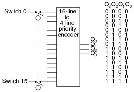
Now, only 4 wires (plus any ground and power wires necessary) are needed to communicate the information, as opposed to 16 wires (plus any ground and power wires). At the monitoring location, we would need some kind of display device that could accept the 4-bit binary data and generate an easy-to-read display for a person to view. A decoder, wired to accept the 4-bit data as its input and light 1-of-16 output lamps, could be used for this task, or we could use a 4-bit decoder/driver circuit to drive some kind of numerical digit display.
Still, a resolution of 1/16 tank height may not be good enough for our application. To better resolve the water level, we need more bits in our binary output. We could add still more switches, but this gets impractical rather quickly. A better option would be to re-attach our original analog transmitter to the tank and electronically convert its 4-20 milliamp analog output into a binary number with far more bits than would be practical using a set of discrete level switches. Since the electrical noise we're trying to avoid is encountered along the long run of wire from the tank to the monitoring location, this A/D conversion can take place at the tank (where we have a "clean" 4-20 mA signal). There are a variety of methods to convert an analog signal to digital, but we'll skip an in-depth discussion of those techniques and concentrate on the digital signal communication itself.
The type of digital information being sent from our tank instrumentation to the monitoring instrumentation is referred to as parallel digital data. That is, each binary bit is being sent along its own dedicated wire, so that all bits arrive at their destination simultaneously. This obviously necessitates the use of at least one wire per bit to communicate with the monitoring location. We could further reduce our wiring needs by sending the binary data along a single channel (one wire + ground), so that each bit is communicated one at a time. This type of information is referred to as serial digital data.
We could use a multiplexer or a shift register to take the parallel data from the A/D converter (at the tank transmitter), and convert it to serial data. At the receiving end (the monitoring location) we could use a demultiplexer or another shift register to convert the serial data to parallel again for use in the display circuitry. The exact details of how the mux/demux or shift register pairs are maintained in synchronization is, like A/D conversion, a topic for another lesson. Fortunately, there are digital IC chips called UARTs (Universal Asynchronous Receiver-Transmitters) that handle all these details on their own and make the designer's life much simpler. For now, we must continue to focus our attention on the matter at hand: how to communicate the digital information from the tank to the monitoring location.
This collection of wires that I keep referring to between the tank and the monitoring location can be called a bus or a network. The distinction between these two terms is more semantic than technical, and the two may be used interchangeably for all practical purposes. In my experience, the term "bus" is usually used in reference to a set of wires connecting digital components within the enclosure of a computer device, and "network" is for something that is physically more widespread. In recent years, however, the word "bus" has gained popularity in describing networks that specialize in interconnecting discrete instrumentation sensors over long distances ("Fieldbus" and "Profibus" are two examples). In either case, we are making reference to the means by which two or more digital devices are connected together so that data can be communicated between them.
Names like "Fieldbus" or "Profibus" encompass not only the physical wiring of the bus or network, but also the specified voltage levels for communication, their timing sequences (especially for serial data transmission), connector pinout specifications, and all other distinguishing technical features of the network. In other words, when we speak of a certain type of bus or network by name, we're actually speaking of a communications standard, roughly analogous to the rules and vocabulary of a written language. For example, before two or more people can become pen-pals, they must be able to write to one another in a common format. To merely have a mail system that is able to deliver their letters to each other is not enough. If they agree to write to each other in French, they agree to hold to the conventions of character set, vocabulary, spelling, and grammar that is specified by the standard of the French language. Likewise, if we connect two Profibus devices together, they will be able to communicate with each other only because the Profibus standard has specified such important details as voltage levels, timing sequences, etc. Simply having a set of wires strung between multiple devices is not enough to construct a working system (especially if the devices were built by different manufacturers!).
To illustrate in detail, let's design our own bus standard. Taking the crude water tank measurement system with five switches to detect varying levels of water, and using (at least) five wires to conduct the signals to their destination, we can lay the foundation for the mighty BogusBus:
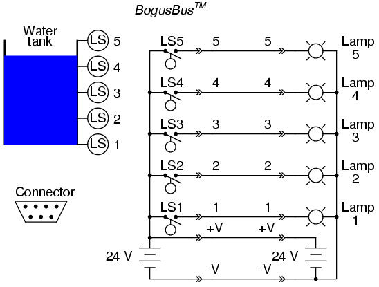
The physical wiring for the BogusBus consists of seven wires between the transmitter device (switches) and the receiver device (lamps). The transmitter consists of all components and wiring connections to the left of the leftmost connectors (the "-->>--" symbols). Each connector symbol represents a complementary male and female element. The bus wiring consists of the seven wires between the connector pairs. Finally, the receiver and all of its constituent wiring lies to the right of the rightmost connectors. Five of the network wires (labeled 1 through 5) carry the data while two of those wires (labeled +V and -V) provide connections for DC power supplies. There is a standard for the 7-pin connector plugs, as well. The pin layout is asymmetrical to prevent "backward" connection.
In order for manufacturers to receive the awe-inspiring "BogusBus-compliant" certification on their products, they would have to comply with the specifications set by the designers of BogusBus (most likely another company, which designed the bus for a specific task and ended up marketing it for a wide variety of purposes). For instance, all devices must be able to use the 24 Volt DC supply power of BogusBus: the switch contacts in the transmitter must be rated for switching that DC voltage, the lamps must definitely be rated for being powered by that voltage, and the connectors must be able to handle it all. Wiring, of course, must be in compliance with that same standard: lamps 1 through 5, for example, must be wired to the appropriate pins so that when LS4 of Manufacturer XYZ's transmitter closes, lamp 4 of Manufacturer ABC's receiver lights up, and so on. Since both transmitter and receiver contain DC power supplies rated at an output of 24 Volts, all transmitter/receiver combinations (from all certified manufacturers) must have power supplies that can be safely wired in parallel. Consider what could happen if Manufacturer XYZ made a transmitter with the negative (-) side of their 24VDC power supply attached to earth ground and Manufacturer ABC made a receiver with the positive (+) side of their 24VDC power supply attached to earth ground. If both earth grounds are relatively "solid" (that is, a low resistance between them, such as might be the case if the two grounds were made on the metal structure of an industrial building), the two power supplies would short-circuit each other!
BogusBus, of course, is a completely hypothetical and very impractical example of a digital network. It has incredibly poor data resolution, requires substantial wiring to connect devices, and communicates in only a single direction (from transmitter to receiver). It does, however, suffice as a tutorial example of what a network is and some of the considerations associated with network selection and operation.
There are many types of buses and networks that you might come across in your profession. Each one has its own applications, advantages, and disadvantages. It is worthwhile to associate yourself with some of the "alphabet soup" that is used to label the various designs:
PC/AT Bus used in early IBM-compatible computers to connect peripheral devices such as disk drive and sound cards to the motherboard of the computer.
PCI Another bus used in personal computers, but not limited to IBM-compatibles. Much faster than PC/AT. Typical data transfer rate of 100 Mbytes/second (32 bit) and 200 Mbytes/second (64 bit).
PCMCIA A bus designed to connect peripherals to laptop and notebook sized personal computers. Has a very small physical "footprint," but is considerably slower than other popular PC buses.
VME A high-performance bus (co-designed by Motorola, and based on Motorola's earlier Versa-Bus standard) for constructing versatile industrial and military computers, where multiple memory, peripheral, and even microprocessor cards could be plugged in to a passive "rack" or "card cage" to facilitate custom system designs. Typical data transfer rate of 50 Mbytes/second (64 bits wide).
VXI Actually an expansion of the VME bus, VXI (VME eXtension for Instrumentation) includes the standard VME bus along with connectors for analog signals between cards in the rack.
S-100 Sometimes called the Altair bus, this bus standard was the product of a conference in 1976, intended to serve as an interface to the Intel 8080 microprocessor chip. Similar in philosophy to the VME, where multiple function cards could be plugged in to a passive "rack," facilitating the construction of custom systems.
MC6800 The Motorola equivalent of the Intel-centric S-100 bus, designed to interface peripheral devices to the popular Motorola 6800 microprocessor chip.
STD Stands for Simple-To-Design, and is yet another passive "rack" similar to the PC/AT bus, and lends itself well toward designs based on IBM-compatible hardware. Designed by Pro-Log, it is 8 bits wide (parallel), accomodating relatively small (4.5 inch by 6.5 inch) circuit cards.
Multibus I and II Another bus intended for the flexible design of custom computer systems, designed by Intel. 16 bits wide (parallel).
CompactPCI An industrial adaptation of the personal computer PCI standard, designed as a higher-performance alternative to the older VME bus. At a bus clock speed of 66 MHz, data transfer rates are 200 Mbytes/ second (32 bit) or 400 Mbytes/sec (64 bit).
Microchannel Yet another bus, this one designed by IBM for their ill-fated PS/2 series of computers, intended for the interfacing of PC motherboards to peripheral devices.
IDE A bus used primarily for connecting personal computer hard disk drives with the appropriate peripheral cards. Widely used in today's personal computers for hard drive and CD-ROM drive interfacing.
SCSI An alternative (technically superior to IDE) bus used for personal computer disk drives. SCSI stands for Small Computer System Interface. Used in some IBM-compatible PC's, as well as Macintosh (Apple), and many mini and mainframe business computers. Used to interface hard drives, CD-ROM drives, floppy disk drives, printers, scanners, modems, and a host of other peripheral devices. Speeds up to 1.5 Mbytes per second for the original standard.
GPIB (IEEE 488) General Purpose Interface Bus, also known as HPIB or IEEE 488, which was intended for the interfacing of electronic test equipment such as oscilloscopes and multimeters to personal computers. 8 bit wide address/data "path" with 8 additional lines for communications control.
Centronics parallel Widely used on personal computers for interfacing printer and plotter devices. Sometimes used to interface with other peripheral devices, such as external ZIP (100 Mbyte floppy) disk drives and tape drives.
USB Universal Serial Bus, which is intended to interconnect many external peripheral devices (such as keyboards, modems, mice, etc.) to personal computers. Long used on Macintosh PC's, it is now being installed as new equipment on IBM-compatible machines.
FireWire (IEEE 1394) A high-speed serial network capable of operating at 100, 200, or 400 Mbps with handy features such as "hot swapping" (adding or removing devices with the power on) and flexible topology. Designed for high-performance personal computer interfacing.
Bluetooth A radio-based communications network designed for office linking of computer devices. Provisions for data security designed into this network standard.
20 mA current loop Not to be confused with the common instrumentation 4-20 mA analog standard, this is a digital communications network based on interrupting a 20 mA (or sometimes 60 mA) current loop to represent binary data. Although the low impedance gives good noise immunity, it is susceptible to wiring faults (such as breaks) which would fail the entire network.
RS-232C The most common serial network used in computer systems, often used to link peripheral devices such as printers and mice to a personal computer. Limited in speed and distance (typically 45 feet and 20 kbps, although higher speeds can be run with shorter distances). I've been able to run RS-232 reliably at speeds in excess of 100 kbps, but this was using a cable only 6 feet long! RS-232C is often referred to simply as RS-232 (no "C").
RS-422A/RS-485 Two serial networks designed to overcome some of the distance and versatility limitations of RS-232C. Used widely in industry to link serial devices together in electrically "noisy" plant environments. Much greater distance and speed limitations than RS-232C, typically over half a mile and at speeds approaching 10 Mbps.
Ethernet (IEEE 802.3) A high-speed network which links computers and some types of peripheral devices together. "Normal" Ethernet runs at a speed of 10 million bits/second, and "Fast" Ethernet runs at 100 million bits/second. The slower (10 Mbps) Ethernet has been implemented in a variety of means on copper wire (thick coax = "10BASE5", thin coax = "10BASE2", twisted-pair = "10BASE-T"), radio, and on optical fiber ("10BASE-F"). The Fast Ethernet has also been implemented on a few different means (twisted-pair, 2 pair = 100BASE-TX; twisted-pair, 4 pair = 100BASE-T4; optical fiber = 100BASE-FX).
Token ring Another high-speed network linking computer devices together, using a philosophy of communication that is much different from Ethernet, allowing for more precise response times from individual network devices, and greater immunity to network wiring damage.
FDDI A very high-speed network exclusively implemented on fiber-optic cabling.
Modbus/Modbus Plus Originally implemented by the Modicon corporation, a large maker of Programmable Logic Controllers (PLCs) for linking remote I/O (Input/Output) racks with a PLC processor. Still quite popular.
Profibus Originally implemented by the Siemens corporation, another large maker of PLC equipment.
Foundation Fieldbus A high-performance bus expressly designed to allow multiple process instruments (transmitters, controllers, valve positioners) to communicate with host computers and with each other. May ultimately displace the 4-20 mA analog signal as the standard means of interconnecting process control instrumentation in the future.
Buses and networks are designed to allow communication to occur between individual devices that are interconnected. The flow of information, or data, between nodes can take a variety of forms:
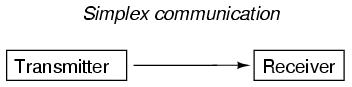
With simplex communication, all data flow is unidirectional: from the designated transmitter to the designated receiver. BogusBus is an example of simplex communication, where the transmitter sent information to the remote monitoring location, but no information is ever sent back to the water tank. If all we want to do is send information one-way, then simplex is just fine. Most applications, however, demand more:
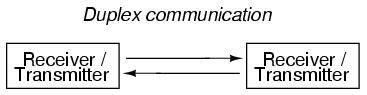
With duplex communication, the flow of information is bidirectional for each device. Duplex can be further divided into two sub-categories:
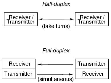
Half-duplex communication may be likened to two tin cans on the ends of a single taut string: Either can may be used to transmit or receive, but not at the same time. Full-duplex communication is more like a true telephone, where two people can talk at the same time and hear one another simultaneously, the mouthpiece of one phone transmitting the the earpiece of the other, and visa-versa. Full-duplex is often facilitated through the use of two separate channels or networks, with an individual set of wires for each direction of communication. It is sometimes accomplished by means of multiple-frequency carrier waves, especially in radio links, where one frequency is reserved for each direction of communication.
With BogusBus, our signals were very simple and straightforward: each signal wire (1 through 5) carried a single bit of digital data, 0 Volts representing "off" and 24 Volts DC representing "on." Because all the bits arrived at their destination simultaneously, we would call BogusBus a parallel network technology. If we were to improve the performance of BogusBus by adding binary encoding (to the transmitter end) and decoding (to the receiver end), so that more steps of resolution were available with fewer wires, it would still be a parallel network. If, however, we were to add a parallel-to-serial converter at the transmitter end and a serial-to-parallel converter at the receiver end, we would have something quite different.
It is primarily with the use of serial technology that we are forced to invent clever ways to transmit data bits. Because serial data requires us to send all data bits through the same wiring channel from transmitter to receiver, it necessitates a potentially high frequency signal on the network wiring. Consider the following illustration: a modified BogusBus system is communicating digital data in parallel, binary-encoded form. Instead of 5 discrete bits like the original BogusBus, we're sending 8 bits from transmitter to receiver. The A/D converter on the transmitter side generates a new output every second. That makes for 8 bits per second of data being sent to the receiver. For the sake of illustration, let's say that the transmitter is bouncing between an output of 10101010 and 10101011 every update (once per second):
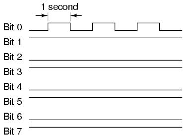
Since only the least significant bit (Bit 1) is changing, the frequency on that wire (to ground) is only 1/2 Hertz. In fact, no matter what numbers are being generated by the A/D converter between updates, the frequency on any wire in this modified BogusBus network cannot exceed 1/2 Hertz, because that's how fast the A/D updates its digital output. 1/2 Hertz is pretty slow, and should present no problems for our network wiring.
On the other hand, if we used an 8-bit serial network, all data bits must appear on the single channel in sequence. And these bits must be output by the transmitter within the 1-second window of time between A/D converter updates. Therefore, the alternating digital output of 10101010 and 10101011 (once per second) would look something like this:

The frequency of our BogusBus signal is now approximately 4 Hertz instead of 1/2 Hertz, an eightfold increase! While 4 Hertz is still fairly slow, and does not constitute an engineering problem, you should be able to appreciate what might happen if we were transmitting 32 or 64 bits of data per update, along with the other bits necessary for parity checking and signal synchronization, at an update rate of thousands of times per second! Serial data network frequencies start to enter the radio range, and simple wires begin to act as antennas, pairs of wires as transmission lines, with all their associated quirks due to inductive and capacitive reactances.
What is worse, the signals that we're trying to communicate along a serial network are of a square-wave shape, being binary bits of information. Square waves are peculiar things, being mathematically equivalent to an infinite series of sine waves of diminishing amplitude and increasing frequency. A simple square wave at 10 kHz is actually "seen" by the capacitance and inductance of the network as a series of multiple sine-wave frequencies which extend into the hundreds of kHz at significant amplitudes. What we receive at the other end of a long 2-conductor network won't look like a clean square wave anymore, even under the best of conditions!
When engineers speak of network bandwidth, they're referring to the practical frequency limit of a network medium. In serial communication, bandwidth is a product of data volume (binary bits per transmitted "word") and data speed ("words" per second). The standard measure of network bandwidth is bits per second, or bps. An obsolete unit of bandwidth known as the baud is sometimes falsely equated with bits per second, but is actually the measure of signal level changes per second. Many serial network standards use multiple voltage or current level changes to represent a single bit, and so for these applications bps and baud are not equivalent.
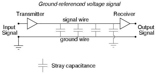
The general BogusBus design, where all bits are voltages referenced to a common "ground" connection, is the worst-case situation for high-frequency square wave data communication. Everything will work well for short distances, where inductive and capacitive effects can be held to a minimum, but for long distances this method will surely be problematic:
A robust alternative to the common ground signal method is the differential voltage method, where each bit is represented by the difference of voltage between a ground-isolated pair of wires, instead of a voltage between one wire and a common ground. This tends to limit the capacitive and inductive effects imposed upon each signal and the tendency for the signals to be corrupted due to outside electrical interference, thereby significantly improving the practical distance of a serial network:
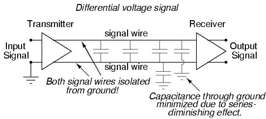
The triangular amplifier symbols represent differential amplifiers, which output a voltage signal between two wires, neither one electrically common with ground. Having eliminated any relation between the voltage signal and ground, the only significant capacitance imposed on the signal voltage is that existing between the two signal wires. Capacitance between a signal wire and a grounded conductor is of much less effect, because the capacitive path between the two signal wires via a ground connection is two capacitances in series (from signal wire #1 to ground, then from ground to signal wire #2), and series capacitance values are always less than any of the individual capacitances. Furthermore, any "noise" voltage induced between the signal wires and earth ground by an external source will be ignored, because that noise voltage will likely be induced on both signal wires in equal measure, and the receiving amplifier only responds to the differential voltage between the two signal wires, rather than the voltage between any one of them and earth ground.
RS-232C is a prime example of a ground-referenced serial network, while RS-422A is a prime example of a differential voltage serial network. RS-232C finds popular application in office environments where there is little electrical interference and wiring distances are short. RS-422A is more widely used in industrial applications where longer wiring distances and greater potential for electrical interference from AC power wiring exists.
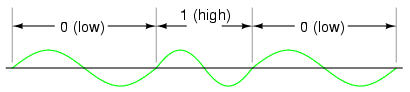
However, a large part of the problem with digital network signals is the square-wave nature of such voltages, as was previously mentioned. If only we could avoid square waves all together, we could avoid many of their inherent difficulties in long, high-frequency networks. One way of doing this is to modulate a sine wave voltage signal with our digital data. "Modulation" means that magnitude of one signal has control over some aspect of another signal. Radio technology has incorporated modulation for decades now, in allowing an audio-frequency voltage signal to control either the amplitude (AM) or frequency (FM) of a much higher frequency "carrier" voltage, which is then send to the antenna for transmission. The frequency-modulation (FM) technique has found more use in digital networks than amplitude-modulation (AM), except that it's referred to as Frequency Shift Keying (FSK). With simple FSK, sine waves of two distinct frequencies are used to represent the two binary states, 1 and 0:
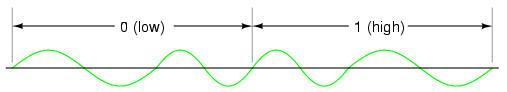
Due to the practical problems of getting the low/high frequency sine waves to begin and end at the zero crossover points for any given combination of 0's and 1's, a variation of FSK called phase-continuous FSK is sometimes used, where the consecutive combination of a low/high frequency represents one binary state and the combination of a high/low frequency represents the other. This also makes for a situation where each bit, whether it be 0 or 1, takes exactly the same amount of time to transmit along the network:
With sine wave signal voltages, many of the problems encountered with square wave digital signals are minimized, although the circuitry required to modulate (and demodulate) the network signals is more complex and expensive.
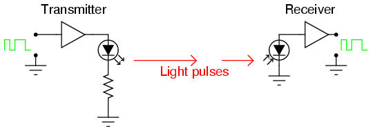
A modern alternative to sending (binary) digital information via electric voltage signals is to use optical (light) signals. Electrical signals from digital circuits (high/low voltages) may be converted into discrete optical signals (light or no light) with LEDs or solid-state lasers. Likewise, light signals can be translated back into electrical form through the use of photodiodes or phototransistors for introduction into the inputs of gate circuits.
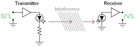
Transmitting digital information in optical form may be done in open air, simply by aiming a laser at a photodetector at a remote distance, but interference with the beam in the form of temperature inversion layers, dust, rain, fog, and other obstructions can present significant engineering problems:
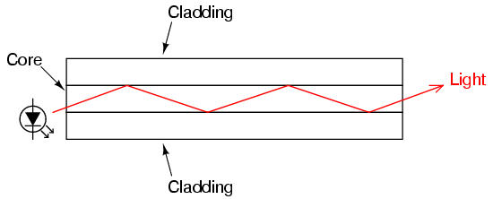
One way to avoid the problems of open-air optical data transmission is to send the light pulses down an ultra-pure glass fiber. Glass fibers will "conduct" a beam of light much as a copper wire will conduct electrons, with the advantage of completely avoiding all the associated problems of inductance, capacitance, and external interference plaguing electrical signals. Optical fibers keep the light beam contained within the fiber core by a phenomenon known as total internal reflectance.
An optical fiber is composed of two layers of ultra-pure glass, each layer made of glass with a slightly different refractive index, or capacity to "bend" light. With one type of glass concentrically layered around a central glass core, light introduced into the central core cannot escape outside the fiber, but is confined to travel within the core:
These layers of glass are very thin, the outer "cladding" typically 125 microns (1 micron = 1 millionth of a meter, or 10-6 meter) in diameter. This thinness gives the fiber considerable flexibility. To protect the fiber from physical damage, it is usually given a thin plastic coating, placed inside of a plastic tube, wrapped with kevlar fibers for tensile strength, and given an outer sheath of plastic similar to electrical wire insulation. Like electrical wires, optical fibers are often bundled together within the same sheath to form a single cable.
Optical fibers exceed the data-handling performance of copper wire in almost every regard. They are totally immune to electromagnetic interference and have very high bandwidths. However, they are not without certain weaknesses.
One weakness of optical fiber is a phenomenon known as microbending. This is where the fiber is bend around too small of a radius, causing light to escape the inner core, through the cladding:
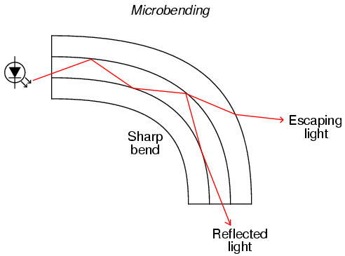
Not only does microbending lead to diminished signal strength due to the lost light, but it also constitutes a security weakness in that a light sensor intentionally placed on the outside of a sharp bend could intercept digital data transmitted over the fiber.
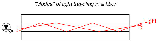
Another problem unique to optical fiber is signal distortion due to multiple light paths, or modes, having different distances over the length of the fiber. When light is emitted by a source, the photons (light particles) do not all travel the exact same path. This fact is patently obvious in any source of light not conforming to a straight beam, but is true even in devices such as lasers. If the optical fiber core is large enough in diameter, it will support multiple pathways for photons to travel, each of these pathways having a slightly different length from one end of the fiber to the other. This type of optical fiber is called multimode fiber:
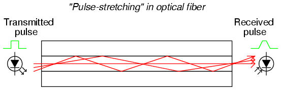
A light pulse emitted by the LED taking a shorter path through the fiber will arrive at the detector sooner than light pulses taking longer paths. The result is distortion of the square-wave's rising and falling edges, called pulse stretching. This problem becomes worse as the overall fiber length is increased:
However, if the fiber core is made small enough (around 5 microns in diameter), light modes are restricted to a single pathway with one length. Fiber so designed to permit only a single mode of light is known as single-mode fiber. Because single-mode fiber escapes the problem of pulse stretching experienced in long cables, it is the fiber of choice for long-distance (several miles or more) networks. The drawback, of course, is that with only one mode of light, single-mode fibers do not conduct as as much light as multimode fibers. Over long distances, this exacerbates the need for "repeater" units to boost light power.
If we want to connect two digital devices with a network, we would have a kind of network known as "point-to-point:"
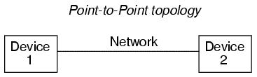
For the sake of simplicity, the network wiring is symbolized as a single line between the two devices. In actuality, it may be a twisted pair of wires, a coaxial cable, an optical fiber, or even a seven-conductor BogusBus. Right now, we're merely focusing on the "shape" of the network, technically known as its topology.
If we want to include more devices (sometimes called nodes) on this network, we have several options of network configuration to choose from:
Many network standards dictate the type of topology which is used, while others are more versatile. Ethernet, for example, is commonly implemented in a "bus" topology but can also be implemented in a "star" or "ring" topology with the appropriate interconnecting equipment. Other networks, such as RS-232C, are almost exclusively point-to-point; and token ring (as you might have guessed) is implemented solely in a ring topology.
Different topologies have different pros and cons associated with them:
Quite obviously the only choice for two nodes.
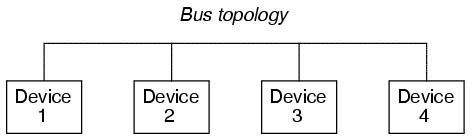
Very simple to install and maintain. Nodes can be easily added or removed with minimal wiring changes. On the other hand, the one bus network must handle all communication signals from all nodes. This is known as broadcast networking, and is analogous to a group of people talking to each other over a single telephone connection, where only one person can talk at a time (limiting data exchange rates), and everyone can hear everyone else when they talk (which can be a data security issue). Also, a break in the bus wiring can lead to nodes being isolated in groups.
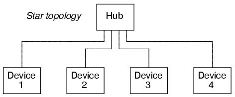
With devices known as "gateways" at branching points in the network, data flow can be restricted between nodes, allowing for private communication between specific groups of nodes. This addresses some of the speed and security issues of the simple bus topology. However, those branches could easily be cut off from the rest of the "star" network if one of the gateways were to fail. Can also be implemented with "switches" to connect individual nodes to a larger network on demand. Such a switched network is similar to the standard telephone system.
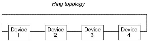
This topology provides the best reliability with the least amount of wiring. Since each node has two connection points to the ring, a single break in any part of the ring doesn't affect the integrity of the network. The devices, however, must be designed with this topology in mind. Also, the network must be interrupted to install or remove nodes. As with bus topology, ring networks are broadcast by nature.
As you might suspect, two or more ring topologies may be combined to give the "best of both worlds" in a particular application. Quite often, industrial networks end up in this fashion over time, simply from engineers and technicians joining multiple networks together for the benefit of plant-wide information access.
Aside from the issues of the physical network (signal types and voltage levels, connector pinouts, cabling, topology, etc.), there needs to be a standardized way in which communication is arbitrated between multiple nodes in a network, even if it's as simple as a two-node, point-to-point system. When a node "talks" on the network, it is generating a signal on the network wiring, be it high and low DC voltage levels, some kind of modulated AC carrier wave signal, or even pulses of light in a fiber. Nodes that "listen" are simply measuring that applied signal on the network (from the transmitting node) and passively monitoring it. If two or more nodes "talk" at the same time, however, their output signals may clash (imagine two logic gates trying to apply opposite signal voltages to a single line on a bus!), corrupting the transmitted data.
The standardized method by which nodes are allowed to transmit to the bus or network wiring is called a protocol. There are many different protocols for arbitrating the use of a common network between multiple nodes, and I'll cover just a few here. However, it's good to be aware of these few, and to understand why some work better for some purposes than others. Usually, a specific protocol is associated with a standardized type of network. This is merely another "layer" to the set of standards which are specified under the titles of various networks.
The International Standards Organization (ISO) has specified a general architecture of network specifications in their DIS7498 model (applicable to most any digital network). Consisting of seven "layers," this outline attempts to categorize all levels of abstraction necessary to communicate digital data.
Some established network protocols only cover one or a few of the DIS7498 levels. For example, the widely used RS-232C serial communications protocol really only addresses the first ("physical") layer of this seven-layer model. Other protocols, such as the X-windows graphical client/server system developed at MIT for distributed graphic-user-interface computer systems, cover all seven layers.
Different protocols may use the same physical layer standard. An example of this is the RS-422A and RS-485 protocols, both of which use the same differential-voltage transmitter and receiver circuitry, using the same voltage levels to denote binary 1's and 0's. On a physical level, these two communication protocols are identical. However, on a more abstract level the protocols are different: RS-422A is point-to-point only, while RS-485 supports a bus topology "multidrop" with up to 32 addressable nodes.
Perhaps the simplest type of protocol is the one where there is only one transmitter, and all the other nodes are merely receivers. Such is the case for BogusBus, where a single transmitter generates the voltage signals impressed on the network wiring, and one or more receiver units (with 5 lamps each) light up in accord with the transmitter's output. This is always the case with a simplex network: there's only one talker, and everyone else listens!
When we have multiple transmitting nodes, we must orchestrate their transmissions in such a way that they don't conflict with one another. Nodes shouldn't be allowed to talk when another node is talking, so we give each node the ability to "listen" and to refrain from talking until the network is silent. This basic approach is called Carrier Sense Multiple Access (CSMA), and there exists a few variations on this theme. Please note that CSMA is not a standardized protocol in itself, but rather a methodology that certain protocols follow.
One variation is to simply let any node begin to talk as soon as the network is silent. This is analogous to a group of people meeting at a round table: anyone has the ability to start talking, so long as they don't interrupt anyone else. As soon as the last person stops talking, the next person waiting to talk will begin. So, what happens when two or more people start talking at once? In a network, the simultaneous transmission of two or more nodes is called a collision. With CSMA/CD (CSMA/Collision Detection), the nodes that collide simply reset themselves with a random delay timer circuit, and the first one to finish its time delay tries to talk again. This is the basic protocol for the popular Ethernet network.
Another variation of CSMA is CSMA/BA (CSMA/Bitwise Arbitration), where colliding nodes refer to pre-set priority numbers which dictate which one has permission to speak first. In other words, each node has a "rank" which settles any dispute over who gets to start talking first after a collision occurs, much like a group of people where dignitaries and common citizens are mixed. If a collision occurs, the dignitary is generally allowed to speak first and the common person waits afterward.
In either of the two examples above (CSMA/CD and CSMA/BA), we assumed that any node could initiate a conversation so long as the network was silent. This is referred to as the "unsolicited" mode of communication. There is a variation called "solicited" mode for either CSMA/CD or CSMA/BA where the initial transmission is only allowed to occur when a designated master node requests (solicits) a reply. Collision detection (CD) or bitwise arbitration (BA) applies only to post-collision arbitration as multiple nodes respond to the master device's request.
An entirely different strategy for node communication is the Master/Slave protocol, where a single master device allots time slots for all the other nodes on the network to transmit, and schedules these time slots so that multiple nodes cannot collide. The master device addresses each node by name, one at a time, letting that node talk for a certain amount of time. When it is finished, the master addresses the next node, and so on, and so on.
Yet another strategy is the Token-Passing protocol, where each node gets a turn to talk (one at a time), and then grants permission for the next node to talk when it's done. Permission to talk is passed around from node to node as each one hands off the "token" to the next in sequential order. The token itself is not a physical thing: it is a series of binary 1's and 0's broadcast on the network, carrying a specific address of the next node permitted to talk. Although token-passing protocol is often associated with ring-topology networks, it is not restricted to any topology in particular. And when this protocol is implemented in a ring network, the sequence of token passing does not have to follow the physical connection sequence of the ring.
Just as with topologies, multiple protocols may be joined together over different segments of a heterogeneous network, for maximum benefit. For instance, a dedicated Master/Slave network connecting instruments together on the manufacturing plant floor may be linked through a gateway device to an Ethernet network which links multiple desktop computer workstations together, one of those computer workstations acting as a gateway to link the data to an FDDI fiber network back to the plant's mainframe computer. Each network type, topology, and protocol serves different needs and applications best, but through gateway devices, they can all share the same data.
It is also possible to blend multiple protocol strategies into a new hybrid within a single network type. Such is the case for Foundation Fieldbus, which combines Master/Slave with a form of token-passing. A Link Active Scheduler (LAS) device sends scheduled "Compel Data" (CD) commands to query slave devices on the Fieldbus for time-critical information. In this regard, Fieldbus is a Master/Slave protocol. However, when there's time between CD queries, the LAS sends out "tokens" to each of the other devices on the Fieldbus, one at a time, giving them opportunity to transmit any unscheduled data. When those devices are done transmitting their information, they return the token back to the LAS. The LAS also probes for new devices on the Fieldbus with a "Probe Node" (PN) message, which is expected to produce a "Probe Response" (PR) back to the LAS. The responses of devices back to the LAS, whether by PR message or returned token, dictate their standing on a "Live List" database which the LAS maintains. Proper operation of the LAS device is absolutely critical to the functioning of the Fieldbus, so there are provisions for redundant LAS operation by assigning "Link Master" status to some of the nodes, empowering them to become alternate Link Active Schedulers if the operating LAS fails.
Other data communications protocols exist, but these are the most popular. I had the opportunity to work on an old (circa 1975) industrial control system made by Honeywell where a master device called the Highway Traffic Director, or HTD, arbitrated all network communications. What made this network interesting is that the signal sent from the HTD to all slave devices for permitting transmission was not communicated on the network wiring itself, but rather on sets of individual twisted-pair cables connecting the HTD with each slave device. Devices on the network were then divided into two categories: those nodes connected to the HTD which were allowed to initiate transmission, and those nodes not connected to the HTD which could only transmit in response to a query sent by one of the former nodes. Primitive and slow are the only fitting adjectives for this communication network scheme, but it functioned adequately for its time.
A principal consideration for industrial control networks, where the monitoring and control of real-life processes must often occur quickly and at set times, is the guaranteed maximum communication time from one node to another. If you're controlling the position of a nuclear reactor coolant valve with a digital network, you need to be able to guarantee that the valve's network node will receive the proper positioning signals from the control computer at the right times. If not, very bad things could happen!
The ability for a network to guarantee data "throughput" is called determinism. A deterministic network has a guaranteed maximum time delay for data transfer from node to node, whereas a non-deterministic network does not. The preeminent example of a non-deterministic network is Ethernet, where the nodes rely on random time-delay circuits to reset and re-attempt transmission after a collision. Being that a node's transmission of data could be delayed indefinitely from a long series of re-sets and re-tries after repeated collisions, there is no guarantee that its data will ever get sent out to the network. Realistically though, the odds are so astronomically great that such a thing would happen that it is of little practical concern in a lightly-loaded network.
Another important consideration, especially for industrial control networks, is network fault tolerance: that is, how susceptible is a particular network's signaling, topology, and/or protocol to failures? We've already briefly discussed some of the issues surrounding topology, but protocol impacts reliability just as much. For example, a Master/Slave network, while being extremely deterministic (a good thing for critical controls), is entirely dependent upon the master node to keep everything going (generally a bad thing for critical controls). If the master node fails for any reason, none of the other nodes will be able to transmit any data at all, because they'll never receive their alloted time slot permissions to do so, and the whole system will fail.
A similar issue surrounds token-passing systems: what happens if the node holding the token were to fail before passing the token on to the next node? Some token-passing systems address this possibility by having a few designated nodes generate a new token if the network is silent for too long. This works fine if a node holding the token dies, but it causes problems if part of a network falls silent because a cable connection comes undone: the portion of the network that falls silent generates its own token after awhile, and you essentially are left with two smaller networks with one token that's getting passed around each of them to sustain communication. Trouble occurs, however, if that cable connection gets plugged back in: those two segmented networks are joined in to one again, and now there's two tokens being passed around one network, resulting in nodes' transmissions colliding!
There is no "perfect network" for all applications. The task of the engineer and technician is to know the application and know the operations of the network(s) available. Only then can efficient system design and maintenance become a reality.