


"One microampere flowing in one ohm causes a one microvolt potential drop."
Georg Simon Ohm
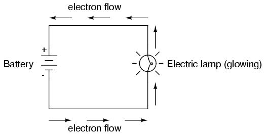
An electric circuit is formed when a conductive path is created to allow free electrons to continuously move. This continuous movement of free electrons through the conductors of a circuit is called a current, and it is often referred to in terms of "flow," just like the flow of a liquid through a hollow pipe.
The force motivating electrons to "flow" in a circuit is called voltage. Voltage is a specific measure of potential energy that is always relative between two points. When we speak of a certain amount of voltage being present in a circuit, we are referring to the measurement of how much potential energy exists to move electrons from one particular point in that circuit to another particular point. Without reference to two particular points, the term "voltage" has no meaning.
Free electrons tend to move through conductors with some degree of friction, or opposition to motion. This opposition to motion is more properly called resistance. The amount of current in a circuit depends on the amount of voltage available to motivate the electrons, and also the amount of resistance in the circuit to oppose electron flow. Just like voltage, resistance is a quantity relative between two points. For this reason, the quantities of voltage and resistance are often stated as being "between" or "across" two points in a circuit.
To be able to make meaningful statements about these quantities in circuits, we need to be able to describe their quantities in the same way that we might quantify mass, temperature, volume, length, or any other kind of physical quantity. For mass we might use the units of "pound" or "gram." For temperature we might use degrees Fahrenheit or degrees Celsius. Here are the standard units of measurement for electrical current, voltage, and resistance:
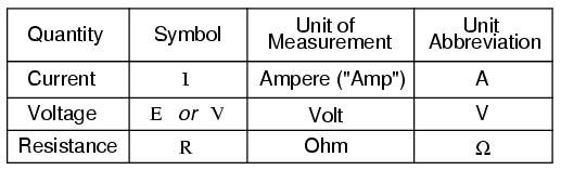
The "symbol" given for each quantity is the standard alphabetical letter used to represent that quantity in an algebraic equation. Standardized letters like these are common in the disciplines of physics and engineering, and are internationally recognized. The "unit abbreviation" for each quantity represents the alphabetical symbol used as a shorthand notation for its particular unit of measurement. And, yes, that strange-looking "horseshoe" symbol is the capital Greek letter Ω, just a character in a foreign alphabet (apologies to any Greek readers here).
Each unit of measurement is named after a famous experimenter in electricity: The amp after the Frenchman Andre M. Ampere, the volt after the Italian Alessandro Volta, and the ohm after the German Georg Simon Ohm.
The mathematical symbol for each quantity is meaningful as well. The "R" for resistance and the "V" for voltage are both self-explanatory, whereas "I" for current seems a bit weird. The "I" is thought to have been meant to represent "Intensity" (of electron flow), and the other symbol for voltage, "E," stands for "Electromotive force." From what research I've been able to do, there seems to be some dispute over the meaning of "I." The symbols "E" and "V" are interchangeable for the most part, although some texts reserve "E" to represent voltage across a source (such as a battery or generator) and "V" to represent voltage across anything else.
All of these symbols are expressed using capital letters, except in cases where a quantity (especially voltage or current) is described in terms of a brief period of time (called an "instantaneous" value). For example, the voltage of a battery, which is stable over a long period of time, will be symbolized with a capital letter "E," while the voltage peak of a lightning strike at the very instant it hits a power line would most likely be symbolized with a lower-case letter "e" (or lower-case "v") to designate that value as being at a single moment in time. This same lower-case convention holds true for current as well, the lower-case letter "i" representing current at some instant in time. Most direct-current (DC) measurements, however, being stable over time, will be symbolized with capital letters.
One foundational unit of electrical measurement, often taught in the beginnings of electronics courses but used infrequently afterwards, is the unit of the coulomb, which is a measure of electric charge proportional to the number of electrons in an imbalanced state. One coulomb of charge is equal to 6,250,000,000,000,000,000 electrons. The symbol for electric charge quantity is the capital letter "Q," with the unit of coulombs abbreviated by the capital letter "C." It so happens that the unit for electron flow, the amp, is equal to 1 coulomb of electrons passing by a given point in a circuit in 1 second of time. Cast in these terms, current is the rate of electric charge motion through a conductor.
As stated before, voltage is the measure of potential energy per unit charge available to motivate electrons from one point to another. Before we can precisely define what a "volt" is, we must understand how to measure this quantity we call "potential energy." The general metric unit for energy of any kind is the joule, equal to the amount of work performed by a force of 1 newton exerted through a motion of 1 meter (in the same direction). In British units, this is slightly less than 3/4 pound of force exerted over a distance of 1 foot. Put in common terms, it takes about 1 joule of energy to lift a 3/4 pound weight 1 foot off the ground, or to drag something a distance of 1 foot using a parallel pulling force of 3/4 pound. Defined in these scientific terms, 1 volt is equal to 1 joule of electric potential energy per (divided by) 1 coulomb of charge. Thus, a 9 volt battery releases 9 joules of energy for every coulomb of electrons moved through a circuit.
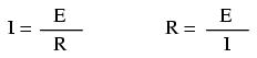
The units and symbols for electrical quantities will become very important to know as we begin to explore the relationships between them in circuits. The first, and perhaps most important, relationship between current, voltage, and resistance is called Ohm's Law. This Law describes how the three quantities interrelate:

In this algebraic expression, voltage (E) is equal to current (I) multiplied by resistance (R). Using algebra techniques, we can manipulate this equation into two variations, solving for I and for R, respectively:
Let's see how these equations might work to help us analyze simple circuits:
In the above circuit, there is only one source of voltage (the battery, on the left) and only one source of resistance to current (the lamp, on the right). This makes it very easy to apply Ohm's Law. If we know the values of any two of the three quantities (voltage, current, and resistance) in this circuit, we can use Ohm's Law to determine the third.
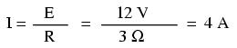
In this first example, we will calculate the amount of current (I) in a circuit, given values of voltage (E) and resistance (R):
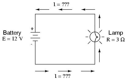
What is the amount of current (I) in this circuit?
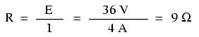
In this second example, we will calculate the amount of resistance (R) in a circuit, given values of voltage (E) and current (I):
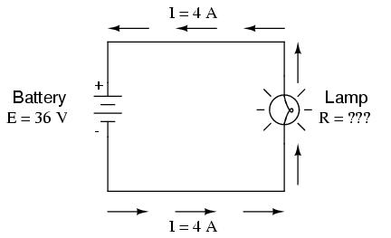
What is the amount of resistance (R) offered by the lamp?
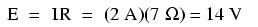
In the last example, we will calculate the amount of voltage supplied by a battery, given values of current (I) and resistance (R):
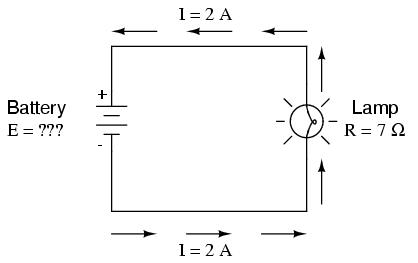
What is the amount of voltage provided by the battery?
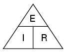
Ohm's Law is a very simple and useful tool for analyzing electric circuits. It is used so often in the study of electricity and electronics that it needs to be committed to memory by the serious student. For those who are not yet comfortable with algebra, there's a trick to remembering how to solve for any one quantity, given the other two. First, arrange the letters E, I, and R in a triangle like this:
If you know E and I, and wish to determine R, just eliminate R from the picture and see what's left:

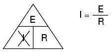
If you know E and R, and wish to determine I, eliminate I and see what's left:
Lastly, if you know I and R, and wish to determine E, eliminate E and see what's left:

Eventually, you'll have to be familiar with algebra to seriously study electricity and electronics, but this tip can make your first calculations a little easier to remember. If you are comfortable with algebra, all you need to do is commit E=IR to memory and derive the other two formulae from that when you need them!
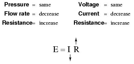
Ohm's Law also make intuitive sense if you apply if to the water-and-pipe analogy. If we have a water pump that exerts pressure (voltage) to push water around a "circuit" (current) through a restriction (resistance), we can model how the three variables interrelate. If the resistance to water flow stays the same and the pump pressure increases, the flow rate must also increase.
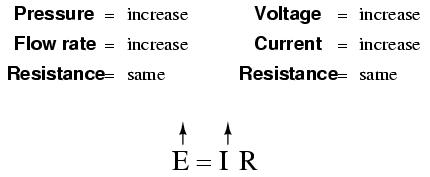
If the pressure stays the same and the resistance increases (making it more difficult for the water to flow), then the flow rate must decrease:
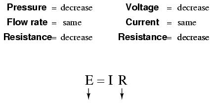
If the flow rate were to stay the same while the resistance to flow decreased, the required pressure from the pump would necessarily decrease:
As odd as it may seem, the actual mathematical relationship between pressure, flow, and resistance is actually more complex for fluids like water than it is for electrons. If you pursue further studies in physics, you will discover this for yourself. Thankfully for the electronics student, the mathematics of Ohm's Law is very straightforward and simple.
In addition to voltage and current, there is another measure of free electron activity in a circuit: power. First, we need to understand just what power is before we analyze it in any circuits.
Power is a measure of how much work can be performed in a given amount of time. Work is generally defined in terms of the lifting of a weight against the pull of gravity. The heavier the weight and/or the higher it is lifted, the more work has been done. Power is a measure of how rapidly a standard amount of work is done.
For American automobiles, engine power is rated in a unit called "horsepower," invented initially as a way for steam engine manufacturers to quantify the working ability of their machines in terms of the most common power source of their day: horses. One horsepower is defined in British units as 550 ft-lbs of work per second of time. The power of a car's engine won't indicate how tall of a hill it can climb or how much weight it can tow, but it will indicate how fast it can climb a specific hill or tow a specific weight.
The power of a mechanical engine is a function of both the engine's speed and it's torque provided at the output shaft. Speed of an engine's output shaft is measured in revolutions per minute, or RPM. Torque is the amount of twisting force produced by the engine, and it is usually measured in pound-feet, or lb-ft (not to be confused with foot-pounds or ft-lbs, which is the unit for work). Neither speed nor torque alone is a measure of an engine's power.
A 100 horsepower diesel tractor engine will turn relatively slowly, but provide great amounts of torque. A 100 horsepower motorcycle engine will turn very fast, but provide relatively little torque. Both will produce 100 horsepower, but at different speeds and different torques. The equation for shaft horsepower is simple:
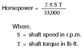
Notice how there are only two variable terms on the right-hand side of the equation, S and T. All the other terms on that side are constant: 2, pi, and 33,000 are all constants (they do not change in value). The horsepower varies only with changes in speed and torque, nothing else. We can re-write the equation to show this relationship:
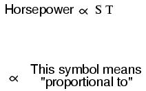
Because the unit of the "horsepower" doesn't coincide exactly with speed in revolutions per minute multiplied by torque in pound-feet, we can't say that horsepower equals ST. However, they are proportional to one another. As the mathematical product of ST changes, the value for horsepower will change by the same proportion.
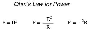
In electric circuits, power is a function of both voltage and current. Not surprisingly, this relationship bears striking resemblance to the "proportional" horsepower formula above:

In this case, however, power (P) is exactly equal to current (I) multiplied by voltage (E), rather than merely being proportional to IE. When using this formula, the unit of measurement for power is the watt, abbreviated with the letter "W."
It must be understood that neither voltage nor current by themselves constitute power. Rather, power is the combination of both voltage and current in a circuit. Remember that voltage is the specific work (or potential energy) per unit charge, while current is the rate at which electric charges move through a conductor. Voltage (specific work) is analogous to the work done in lifting a weight against the pull of gravity. Current (rate) is analogous to the speed at which that weight is lifted. Together as a product (multiplication), voltage (work) and current (rate) constitute power.
Just as in the case of the diesel tractor engine and the motorcycle engine, a circuit with high voltage and low current may be dissipating the same amount of power as a circuit with low voltage and high current. Neither the amount of voltage alone nor the amount of current alone indicates the amount of power in an electric circuit.
In an open circuit, where voltage is present between the terminals of the source and there is zero current, there is zero power dissipated, no matter how great that voltage may be. Since P=IE and I=0 and anything multiplied by zero is zero, the power dissipated in any open circuit must be zero. Likewise, if we were to have a short circuit constructed of a loop of superconducting wire (absolutely zero resistance), we could have a condition of current in the loop with zero voltage, and likewise no power would be dissipated. Since P=IE and E=0 and anything multiplied by zero is zero, the power dissipated in a superconducting loop must be zero. (We'll be exploring the topic of superconductivity in a later chapter).
Whether we measure power in the unit of "horsepower" or the unit of "watt," we're still talking about the same thing: how much work can be done in a given amount of time. The two units are not numerically equal, but they express the same kind of thing. In fact, European automobile manufacturers typically advertise their engine power in terms of kilowatts (kW), or thousands of watts, instead of horsepower! These two units of power are related to each other by a simple conversion formula:

So, our 100 horsepower diesel and motorcycle engines could also be rated as "74570 watt" engines, or more properly, as "74.57 kilowatt" engines. In European engineering specifications, this rating would be the norm rather than the exception.
We've seen the formula for determining the power in an electric circuit: by multiplying the voltage in "volts" by the current in "amps" we arrive at an answer in "watts." Let's apply this to a circuit example:

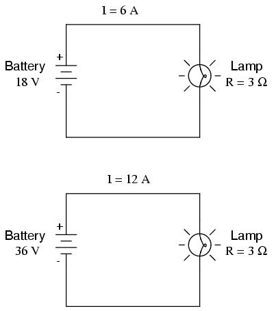
In the above circuit, we know we have a battery voltage of 18 volts and a lamp resistance of 3 Ω. Using Ohm's Law to determine current, we get:
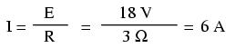
Now that we know the current, we can take that value and multiply it by the voltage to determine power:
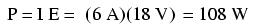
Answer: the lamp is dissipating (releasing) 108 watts of power, most likely in the form of both light and heat.
Let's try taking that same circuit and increasing the battery voltage to see what happens. Intuition should tell us that the circuit current will increase as the voltage increases and the lamp resistance stays the same. Likewise, the power will increase as well:
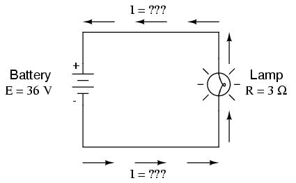
Now, the battery voltage is 36 volts instead of 18 volts. The lamp is still providing 3 Ω of electrical resistance to the flow of electrons. The current is now:
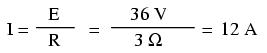
This stands to reason: if I = E/R, and we double E while R stays the same, the current should double. Indeed, it has: we now have 12 amps of current instead of 6. Now, what about power?

Notice that the power has increased just as we might have suspected, but it increased quite a bit more than the current. Why is this? Because power is a function of voltage multiplied by current, and both voltage and current doubled from their previous values, the power will increase by a factor of 2 x 2, or 4. You can check this by dividing 432 watts by 108 watts and seeing that the ratio between them is indeed 4.
Using algebra again to manipulate the formulae, we can take our original power formula and modify it for applications where we don't know both voltage and resistance:
If we only know voltage (E) and resistance (R):

If we only know current (I) and resistance (R):
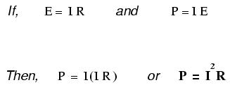
So, in the end, we have these three Ohm's Law equations for electric power in a circuit:
Because the relationship between voltage, current, and resistance in any circuit is so regular, we can reliably control any variable in a circuit simply by controlling the other two. Perhaps the easiest variable in any circuit to control is its resistance. This can be done by changing the material, size, and shape of its conductive components (remember how the thin metal filament of a lamp created more electrical resistance than a thick wire?).
Special components called resistors are made for the express purpose of creating a precise quantity of resistance for insertion into a circuit. They are typically constructed of metal wire or carbon, and engineered to maintain a stable resistance value over a wide range of environmental conditions. Unlike lamps, they do not produce light, but they do produce heat as electric power is dissipated by them in a working circuit. Typically, though, the purpose of a resistor is not to produce usable heat, but simply to provide a precise quantity of electrical resistance.
The most common schematic symbol for a resistor is a zig-zag line:

Resistor values in ohms are usually shown as an adjacent number, and if several resistors are present in a circuit, they will be labeled with a unique identifier number such as R1, R2, R3, etc. As you can see, resistor symbols can be shown either horizontally or vertically:

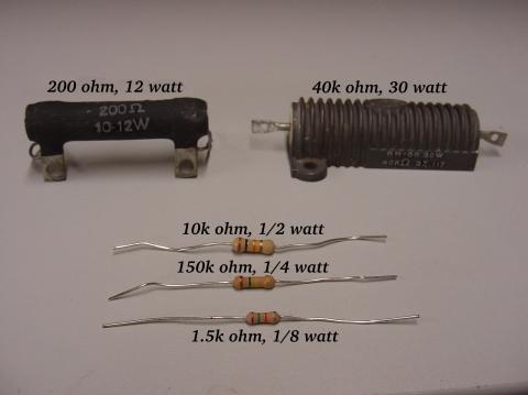
Real resistors look nothing like the zig-zag symbol. Instead, they look like small tubes or cylinders with two wires protruding for connection to a circuit. Here is a sampling of different kinds and sizes of resistors:
In keeping more with their physical appearance, an alternative schematic symbol for a resistor looks like a small, rectangular box:

Resistors can also be shown to have varying rather than fixed resistances. This might be for the purpose of describing an actual physical device designed for the purpose of providing an adjustable resistance, or it could be to show some component that just happens to have an unstable resistance:
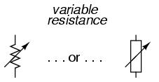
In fact, any time you see a component symbol drawn with a diagonal arrow through it, that component has a variable rather than a fixed value. This symbol "modifier" (the diagonal arrow) is standard electronic symbol convention.
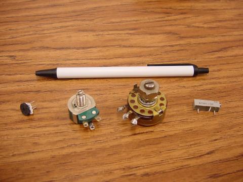
Variable resistors must have some physical means of adjustment, either a rotating shaft or lever that can be moved to vary the amount of electrical resistance. Here is a photograph showing some devices called potentiometers, which can be used as variable resistors:
Because resistors dissipate heat energy as the electric currents through them overcome the "friction" of their resistance, resistors are also rated in terms of how much heat energy they can dissipate without overheating and sustaining damage. Naturally, this power rating is specified in the physical unit of "watts." Most resistors found in small electronic devices such as portable radios are rated at 1/4 (0.25) watt or less. The power rating of any resistor is roughly proportional to its physical size. Note in the first resistor photograph how the power ratings relate with size: the bigger the resistor, the higher its power dissipation rating. Also note how resistances (in ohms) have nothing to do with size!
Although it may seem pointless now to have a device doing nothing but resisting electric current, resistors are extremely useful devices in circuits. Because they are simple and so commonly used throughout the world of electricity and electronics, we'll spend a considerable amount of time analyzing circuits composed of nothing but resistors and batteries.
For a practical illustration of resistors' usefulness, examine the photograph below. It is a picture of a "printed circuit board:" a device made of sandwiched layers of insulating phenolic fiber-board and conductive copper strips, into which components may be inserted and connected by a low-temperature welding process called "soldering." The various components on this circuit board are identified by printed labels. Resistors are denoted by any label beginning with the letter "R".
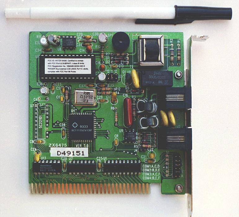
This particular circuit board is a computer accessory called a "modem," which allows digital information transfer over telephone lines. There are at least a dozen resistors (all rated at 1/4 watt power dissipation) that can be seen on this modem's board. Every one of the black rectangles (called "integrated circuits" or "chips") contain their own array of resistors for their internal functions, as well.
Another circuit board example shows resistors packaged in even smaller units, called "surface mount devices." This particular circuit board is the underside of a personal computer hard disk drive, and once again the resistors soldered onto it are designated with labels beginning with the letter "R":
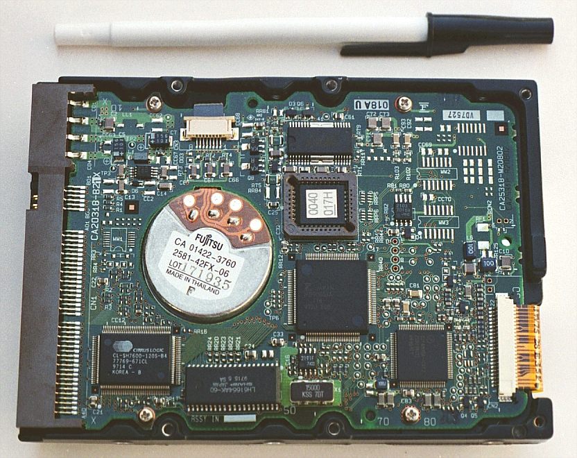
There are over one hundred surface-mount resistors on this circuit board, and this count of course does not include the number of resistors internal to the black "chips." These two photographs should convince anyone that resistors -- devices that "merely" oppose the flow of electrons -- are very important components in the realm of electronics!
In schematic diagrams, resistor symbols are sometimes used to illustrate any general type of device in a circuit doing something useful with electrical energy. Any nonspecific electrical device is generally called a load, so if you see a schematic diagram showing a resistor symbol labeled "load," especially in a tutorial circuit diagram explaining some concept unrelated to the actual use of electrical power, that symbol may just be a kind of shorthand representation of something else more practical than a resistor.
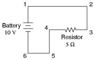
To summarize what we've learned in this lesson, let's analyze the following circuit, determining all that we can from the information given:
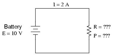
All we've been given here to start with is the battery voltage (10 volts) and the circuit current (2 amps). We don't know the resistor's resistance in ohms or the power dissipated by it in watts. Surveying our array of Ohm's Law equations, we find two equations that give us answers from known quantities of voltage and current:
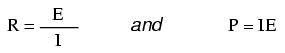
Inserting the known quantities of voltage (E) and current (I) into these two equations, we can determine circuit resistance (R) and power dissipation (P):
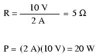
For the circuit conditions of 10 volts and 2 amps, the resistor's resistance must be 5 Ω. If we were designing a circuit to operate at these values, we would have to specify a resistor with a minimum power rating of 20 watts, or else it would overheat and fail.
"Advances are made by answering questions. Discoveries are made by questioning answers."
Bernhard Haisch, Astrophysicist
Ohm's Law is a simple and powerful mathematical tool for helping us analyze electric circuits, but we must realize that reality is not always as simple as the mathematical techniques people devise to explain it. For most conductors, resistance is a rather stable property, largely unaffected by voltage or current. For this reason, we can regard the resistance of most circuit components as a constant, with voltage and current being inversely related to each other.
For instance, our previous circuit example with the 3 Ω lamp, we calculated current through the circuit by dividing voltage by resistance (I=E/R). With an 18 volt battery, our circuit current was 6 amps. Doubling the battery voltage to 36 volts resulted in a doubled current of 12 amps. All of this makes sense, of course, so long as the lamp continues to provide exactly the same amount of friction to the flow of electrons through it: 3 Ω.
However, reality is not always this simple. One of the phenomena explored in a later chapter is that of conductor resistance changing with temperature. In an incandescent lamp (the kind employing the principle of electric current heating a thin filament of wire to the point that it glows white-hot), the resistance of the filament wire will increase dramatically as it warms from room temperature to operating temperature. If we were to increase the supply voltage in a real lamp circuit, the resulting increase in current would cause the filament to increase temperature, which would in turn increase its resistance, thus preventing further increases in current without further increases in battery voltage. Consequently, voltage and current do not follow the simple model predicted by Ohm's Law in this circuit with a stable resistance value of 3 Ω, because an incandescent lamp's filament resistance does not remain stable for different currents.
The phenomenon of resistance changing with variations in temperature is one shared by almost all metals, of which most wires are made. For most applications, these changes in resistance are small enough to be ignored. In the application of metal lamp filaments, the change happens to be quite large.
This is just one example of "nonlinearity" in electric circuits. It is by no means the only example. A "linear" function in mathematics is one that tracks a straight line when plotted on a graph. The simplified version of the lamp circuit with a constant filament resistance of 3 Ω generates a plot like this:
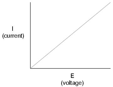
The straight-line plot of current over voltage indicates that resistance is a stable, unchanging value for a wide range of circuit voltages and currents. In an "ideal" situation, this is the case. Resistors, which are manufactured to provide a definite, stable value of resistance, behave very much like the plot of values seen above. A mathematician would call their behavior "linear."
A more realistic analysis of a lamp circuit, however, over several different values of battery voltage would generate a plot of this shape:
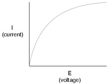
The plot is no longer a straight line. It rises sharply on the left, as voltage increases from zero to a low level. As it progresses to the right we see the line flattening out, the circuit requiring greater and greater increases in voltage to achieve equal increases in current.
If we try to apply Ohm's Law to find the resistance of this lamp circuit with the voltage and current values plotted above, we arrive at several different values. We could say that the resistance here is nonlinear, increasing with increasing current and voltage. The nonlinearity is caused by the effects of high temperature on the metal wire of the lamp filament.
Another example of nonlinear current conduction is through gases such as air. At standard temperatures and pressures, air is an effective insulator. However, if the voltage between two conductors separated by an air gap is increased greatly enough, the air molecules between the gap will become "ionized," having their electrons stripped off by the force of the high voltage between the wires. Once ionized, air (and other gases) become good conductors of electricity, allowing electron flow where none could exist prior to ionization. If we were to plot current over voltage on a graph as we did with the lamp circuit, the effect of ionization would be clearly seen as nonlinear:
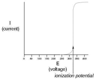
The graph shown is approximate for a small air gap (less than one inch). A larger air gap would yield a higher ionization potential, but the shape of the I/E curve would be very similar: practically no current until the ionization potential was reached, then substantial conduction after that.
Incidentally, this is the reason lightning bolts exist as momentary surges rather than continuous flows of electrons. The voltage built up between the earth and clouds (or between different sets of clouds) must increase to the point where it overcomes the ionization potential of the air gap before the air ionizes enough to support a substantial flow of electrons. Once it does, the current will continue to conduct through the ionized air until the static charge between the two points depletes. Once the charge depletes enough so that the voltage falls below another threshold point, the air de-ionizes and returns to its normal state of extremely high resistance.
Many solid insulating materials exhibit similar resistance properties: extremely high resistance to electron flow below some critical threshold voltage, then a much lower resistance at voltages beyond that threshold. Once a solid insulating material has been compromised by high-voltage breakdown, as it is called, it often does not return to its former insulating state, unlike most gases. It may insulate once again at low voltages, but its breakdown threshold voltage will have been decreased to some lower level, which may allow breakdown to occur more easily in the future. This is a common mode of failure in high-voltage wiring: insulation damage due to breakdown. Such failures may be detected through the use of special resistance meters employing high voltage (1000 volts or more).
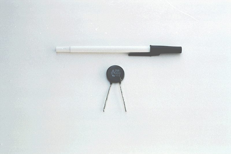
There are circuit components specifically engineered to provide nonlinear resistance curves, one of them being the varistor. Commonly manufactured from compounds such as zinc oxide or silicon carbide, these devices maintain high resistance across their terminals until a certain "firing" or "breakdown" voltage (equivalent to the "ionization potential" of an air gap) is reached, at which point their resistance decreases dramatically. Unlike the breakdown of an insulator, varistor breakdown is repeatable: that is, it is designed to withstand repeated breakdowns without failure. A picture of a varistor is shown here:
There are also special gas-filled tubes designed to do much the same thing, exploiting the very same principle at work in the ionization of air by a lightning bolt.
Other electrical components exhibit even stranger current/voltage curves than this. Some devices actually experience a decrease in current as the applied voltage increases. Because the slope of the current/voltage for this phenomenon is negative (angling down instead of up as it progresses from left to right), it is known as negative resistance.
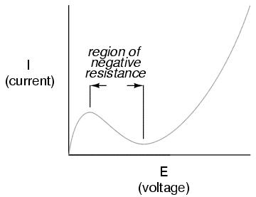
Most notably, high-vacuum electron tubes known as tetrodes and semiconductor diodes known as Esaki or tunnel diodes exhibit negative resistance for certain ranges of applied voltage.
Ohm's Law is not very useful for analyzing the behavior of components like these where resistance is not constant. Some have even suggested that "Ohm's Law" should be demoted from the status of a "Law" because it is not universal. It might be more accurate to call the equation (R=E/I) a definition of resistance, befitting of a certain class of materials under a narrow range of conditions.
For the benefit of the student, however, we will assume that resistances specified in example circuits are stable over a wide range of conditions unless otherwise specified. I just wanted to expose you to a little bit of the complexity of the real world, lest I give you the false impression that the whole of electrical phenomena could be summarized in a few simple Ohm's Law equations.
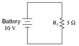
So far, we've been analyzing single-battery, single-resistor circuits with no regard for the connecting wires between the components, so long as a complete circuit is formed. Does the wire length or circuit "shape" matter to our calculations? Let's look at a couple of circuit configurations and find out:

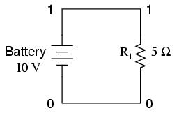
When we draw wires connecting points in a circuit, we usually assume those wires have negligible resistance. As such, they contribute no appreciable effect to the overall resistance of the circuit, and so the only resistance we have to contend with is the resistance in the components. In the above circuits, the only resistance comes from the 5 Ω resistors, so that is all we will consider in our calculations. In real life, metal wires actually do have resistance (and so do power sources!), but those resistances are generally so much smaller than the resistance present in the other circuit components that they can be safely ignored. Exceptions to this rule exist in power system wiring, where even very small amounts of conductor resistance can create significant voltage drops given normal (high) levels of current.
If connecting wire resistance is very little or none, we can regard the connected points in a circuit as being electrically common. That is, points 1 and 2 in the above circuits may be physically joined close together or far apart, and it doesn't matter for any voltage or resistance measurements relative to those points. The same goes for points 3 and 4. It is as if the ends of the resistor were attached directly across the terminals of the battery, so far as our Ohm's Law calculations and voltage measurements are concerned. This is useful to know, because it means you can re-draw a circuit diagram or re-wire a circuit, shortening or lengthening the wires as desired without appreciably impacting the circuit's function. All that matters is that the components attach to each other in the same sequence.
It also means that voltage measurements between sets of "electrically common" points will be the same. That is, the voltage between points 1 and 4 (directly across the battery) will be the same as the voltage between points 2 and 3 (directly across the resistor). Take a close look at the following circuit, and try to determine which points are common to each other:
Here, we only have 2 components excluding the wires: the battery and the resistor. Though the connecting wires take a convoluted path in forming a complete circuit, there are several electrically common points in the electrons' path. Points 1, 2, and 3 are all common to each other, because they're directly connected together by wire. The same goes for points 4, 5, and 6.
The voltage between points 1 and 6 is 10 volts, coming straight from the battery. However, since points 5 and 4 are common to 6, and points 2 and 3 common to 1, that same 10 volts also exists between these other pairs of points:
Between points 1 and 4 = 10 volts
Between points 2 and 4 = 10 volts
Between points 3 and 4 = 10 volts (directly across the resistor)
Between points 1 and 5 = 10 volts
Between points 2 and 5 = 10 volts
Between points 3 and 5 = 10 volts
Between points 1 and 6 = 10 volts (directly across the battery)
Between points 2 and 6 = 10 volts
Between points 3 and 6 = 10 volts
Since electrically common points are connected together by (zero resistance) wire, there is no significant voltage drop between them regardless of the amount of current conducted from one to the next through that connecting wire. Thus, if we were to read voltages between common points, we should show (practically) zero:
Between points 1 and 2 = 0 volts    Points 1, 2, and 3 are
Between points 2 and 3 = 0 volts     electrically common
Between points 1 and 3 = 0 volts

Between points 4 and 5 = 0 volts    Points 4, 5, and 6 are
Between points 5 and 6 = 0 volts     electrically common
Between points 4 and 6 = 0 volts
This makes sense mathematically, too. With a 10 volt battery and a 5 Ω resistor, the circuit current will be 2 amps. With wire resistance being zero, the voltage drop across any continuous stretch of wire can be determined through Ohm's Law as such:
It should be obvious that the calculated voltage drop across any uninterrupted length of wire in a circuit where wire is assumed to have zero resistance will always be zero, no matter what the magnitude of current, since zero multiplied by anything equals zero.
Because common points in a circuit will exhibit the same relative voltage and resistance measurements, wires connecting common points are often labeled with the same designation. This is not to say that the terminal connection points are labeled the same, just the connecting wires. Take this circuit as an example:
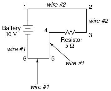
Points 1, 2, and 3 are all common to each other, so the wire connecting point 1 to 2 is labeled the same (wire 2) as the wire connecting point 2 to 3 (wire 2). In a real circuit, the wire stretching from point 1 to 2 may not even be the same color or size as the wire connecting point 2 to 3, but they should bear the exact same label. The same goes for the wires connecting points 6, 5, and 4.
Knowing that electrically common points have zero voltage drop between them is a valuable troubleshooting principle. If I measure for voltage between points in a circuit that are supposed to be common to each other, I should read zero. If, however, I read substantial voltage between those two points, then I know with certainty that they cannot be directly connected together. If those points are supposed to be electrically common but they register otherwise, then I know that there is an "open failure" between those points.
One final note: for most practical purposes, wire conductors can be assumed to possess zero resistance from end to end. In reality, however, there will always be some small amount of resistance encountered along the length of a wire, unless it's a superconducting wire. Knowing this, we need to bear in mind that the principles learned here about electrically common points are all valid to a large degree, but not to an absolute degree. That is, the rule that electrically common points are guaranteed to have zero voltage between them is more accurately stated as such: electrically common points will have very little voltage dropped between them. That small, virtually unavoidable trace of resistance found in any piece of connecting wire is bound to create a small voltage across the length of it as current is conducted through. So long as you understand that these rules are based upon ideal conditions, you won't be perplexed when you come across some condition appearing to be an exception to the rule.
We can trace the direction that electrons will flow in the same circuit by starting at the negative (-) terminal and following through to the positive (+) terminal of the battery, the only source of voltage in the circuit. From this we can see that the electrons are moving counter-clockwise, from point 6 to 5 to 4 to 3 to 2 to 1 and back to 6 again.
As the current encounters the 5 Ω resistance, voltage is dropped across the resistor's ends. The polarity of this voltage drop is negative (-) at point 4 with respect to positive (+) at point 3. We can mark the polarity of the resistor's voltage drop with these negative and positive symbols, in accordance with the direction of current (whichever end of the resistor the current is entering is negative with respect to the end of the resistor it is exiting:
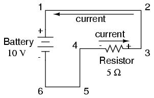
We could make our table of voltages a little more complete by marking the polarity of the voltage for each pair of points in this circuit:
Between points 1 (+) and 4 (-) = 10 volts
Between points 2 (+) and 4 (-) = 10 volts
Between points 3 (+) and 4 (-) = 10 volts
Between points 1 (+) and 5 (-) = 10 volts
Between points 2 (+) and 5 (-) = 10 volts
Between points 3 (+) and 5 (-) = 10 volts
Between points 1 (+) and 6 (-) = 10 volts
Between points 2 (+) and 6 (-) = 10 volts
Between points 3 (+) and 6 (-) = 10 volts
While it might seem a little silly to document polarity of voltage drop in this circuit, it is an important concept to master. It will be critically important in the analysis of more complex circuits involving multiple resistors and/or batteries.
It should be understood that polarity has nothing to do with Ohm's Law: there will never be negative voltages, currents, or resistance entered into any Ohm's Law equations! There are other mathematical principles of electricity that do take polarity into account through the use of signs (+ or -), but not Ohm's Law.
Computers can be powerful tools if used properly, especially in the realms of science and engineering. Software exists for the simulation of electric circuits by computer, and these programs can be very useful in helping circuit designers test ideas before actually building real circuits, saving much time and money.
These same programs can be fantastic aids to the beginning student of electronics, allowing the exploration of ideas quickly and easily with no assembly of real circuits required. Of course, there is no substitute for actually building and testing real circuits, but computer simulations certainly assist in the learning process by allowing the student to experiment with changes and see the effects they have on circuits. Throughout this book, I'll be incorporating computer printouts from circuit simulation frequently in order to illustrate important concepts. By observing the results of a computer simulation, a student can gain an intuitive grasp of circuit behavior without the intimidation of abstract mathematical analysis.
To simulate circuits on computer, I make use of a particular program called SPICE, which works by describing a circuit to the computer by means of a listing of text. In essence, this listing is a kind of program in itself, and must adhere to the syntactical rules of the SPICE language. The computer is then used to run the SPICE program, which reads the text listing describing the circuit and outputs another listing of text containing the results of its detailed mathematical analysis. Many details of using SPICE are described in another volume of this book series for those wanting more information. Here, I'll just introduce the basic concepts and then apply SPICE to the analysis of these simple circuits we've been reading about.
First, we need a circuit for the computer to analyze. Let's try one of the circuits illustrated earlier in the chapter:
This circuit consists of a battery and a resistor connected directly together. We know the voltage of the battery (10 volts) and the resistance of the resistor (5 Ω), but nothing else about the circuit. If we describe this circuit to the computer, it should be able to tell us (at the very least), how much current we have in the circuit.
SPICE demands that all conductors in a circuit be identified with a unique "node" number. Conductors that are electrically common are designated as such by sharing the same number. It might be helpful to think of these numbers as "wire" numbers rather than "node" numbers, following the definition given in the previous section. This is how the computer knows what's connected to what: by the sharing of common numbers. In our example circuit, we only have two "nodes," the top wire and the bottom wire:
SPICE also demands there be a node 0 in the circuit, so we'll label our wires 0 and 1. We can describe the battery to the computer by typing in a line of text starting with the letter "v" (for "Voltage source"), identifying which wire each terminal of the battery connects to (the node numbers), and the battery's voltage, like this:
v 1 0 dc 10
This single line of text tells SPICE that we have a voltage source connected between nodes 1 and 0, direct current (DC), 10 volts. That's all the computer needs to know regarding the battery. Now we turn to the resistor. SPICE requires that resistors be described with a letter "R," the numbers of the two nodes (connection points), and the resistance in ohms. Since this is a computer simulation, there is no need to specify a power rating. That's one nice thing about "virtual" components: they can't be harmed by excessive voltages or currents!
r 1 0 5
There we go: a resistor connected between nodes 1 and 0 with a value of 5 Ω. This very brief line of text tells the computer we have a resistor ("r") connected between the same two nodes as the battery (1 and 0), with a resistance value of 3 Ω.
If we put these two lines of text together, along with a "title" line and an .end statement telling the computer it's reached the end of the circuit description file, we have a complete circuit description ready for processing by the SPICE program. This circuit description, comprised of lines of text in a computer file, is technically known as a netlist, or deck:
first example circuit
v 1 0 dc 10
r 1 0 5
.end
Invoking the SPICE program to process the netlist file, we get the following text output (I've trimmed away a lot of the extraneous details to show you only those bits of information that matter):
first example circuit
v 1 0 dc 10
r 1 0 5
.end
node    voltage
(  1)   10.0000
voltage source currents
name       current
v        -2.000E+00
total power dissipation   2.00E+01  watts
Here, the computer begins with a reiteration of the netlist, complete with title line and .end statement. Then it prints out the voltage at every node with reference to node 0 (in this case, there's only one other node, so it only tells us that). It says there's 10.0000 volts between node 1 and node 0. Then it prints out the current through each voltage source. Again, we only have one voltage source in the entire circuit, so it only tells us the current through that one. In this case, the current equals 2 amps. Due to a quirk in the way SPICE analyzes current, the value of 2 amps gets printed as a negative (-) 2 amps.
The last line of text in the computer's analysis report is "total power dissipation," which in this case is displayed as 2.00 times 10 to the 1st power, watts. In layman's terms, this is 20 watts. SPICE outputs most figures in scientific notation rather than normal (fixed-point) notation. While this may seem to be more confusing at first, it is actually less confusing when really large and really small numbers are involved. The details of scientific notation will be covered in another chapter of this book.
Earlier we explored the consequences of changing one of the three variables in an electric circuit (voltage, current, or resistance) using Ohm's Law to mathematically predict what would happen. Now let's try the same thing using SPICE to do the math for us.
If we were to triple the voltage in our last example circuit from 10 to 30 volts and keep the circuit resistance unchanged, we would expect the current to triple as well. Let's try it:
second example circuit
v 1 0 dc 30
r 1 0 5
.end
node    voltage
(  1)   30.0000
voltage source currents
name       current
v        -6.000E+00
total power dissipation   1.80E+02  watts
Just as we expected, the current tripled with the voltage increase. Current used to be 2 amps, but now it has increased to 6 amps (-6.000 times 10 to the 0th power). Note also how the total power dissipation in the circuit has increased. It was 20 watts before, but now is 180 watts (1.8 times 10 to the 2nd power). Recalling that power was related to the square of the voltage, this makes sense. If we triple the circuit voltage, the power should increase by a factor of nine (three squared). Nine times 20 is indeed 180, so what SPICE is telling us here correlates with what we know about Ohm's Law.
If we want to see how this simple circuit would respond over a wide range of battery voltages, we can invoke some of the fancier options within SPICE. Here, I'll "sweep" the battery voltage from 0 to 100 volts in 5 volt increments, printing out the circuit voltage and current at every step. The lines in the SPICE netlist beginning with a star symbol ("*") are comments. That is, they don't tell the computer to do anything relating to circuit analysis, but merely serve as notes for any human being reading the netlist text.
third example circuit
v 1 0
r 1 0 5
*the ".dc" statement tells spice to sweep the "v" supply
*voltage from 0 to 100 volts in 5 volt steps.
.dc v 0 100 5
.print dc i(v)
.end
v             i(v)
0.000E+00     0.000E+00
5.000E+00    -1.000E+00
1.000E+01    -2.000E+00
1.500E+01    -3.000E+00
2.000E+01    -4.000E+00
2.500E+01    -5.000E+00
3.000E+01    -6.000E+00
3.500E+01    -7.000E+00
4.000E+01    -8.000E+00
4.500E+01    -9.000E+00
5.000E+01    -1.000E+01
5.500E+01    -1.100E+01
6.000E+01    -1.200E+01
6.500E+01    -1.300E+01
7.000E+01    -1.400E+01
7.500E+01    -1.500E+01
8.000E+01    -1.600E+01
8.500E+01    -1.700E+01
9.000E+01    -1.800E+01
9.500E+01    -1.900E+01
1.000E+02    -2.000E+01
The left-hand column of numbers is the battery voltage at each interval, being increased steadily from 0 to 100 volts, 5 volts at a time. The numbers in the right-hand column indicate the circuit current for each of those voltages. Look closely at those numbers and you'll see the proportional relationship between each pair: Ohm's Law (I=E/R) holds true in each case, each current value being 1/5 the respective voltage value, because the circuit resistance is exactly 5 Ω. Again, the negative numbers for current in this SPICE analysis is more of a quirk than anything else. Just pay attention to the absolute value of each number unless otherwise specified.
Whether or not you ever become proficient at using SPICE is not relevant to its application in this book. All that matters is that you acquire a feel for what the numbers mean in the computer's analysis report. In the examples to come, I'll do my best to annotate the numerical results of SPICE to eliminate any confusion, and unlock the power of this amazing tool to help you understand the functioning of electric circuits.