


Whenever an electric voltage exists between two separated conductors, an electric field is present within the space between those conductors. In basic electronics, we study the interactions of voltage, current, and resistance as they pertain to circuits, which are conductive paths through which electrons may travel. When we talk about fields, however, we're dealing with interactions that can be spread across empty space.
Admittedly, the concept of a "field" is somewhat abstract. At least with electric current it isn't too difficult to envision tiny particles called electrons moving their way between the nuclei of atoms within a conductor, but a "field" doesn't even have mass, and need not exist within matter at all.
Despite its abstract nature, almost every one of us has direct experience with fields, at least in the form of magnets. Have you ever played with a pair of magnets, noticing how they attract or repel each other depending on their relative orientation? There is an undeniable force between a pair of magnets, and this force is without "substance." It has no mass, no color, no odor, and if not for the physical force exerted on the magnets themselves, it would be utterly insensible to our bodies. Physicists describe the interaction of magnets in terms of magnetic fields in the space between them. If iron filings are placed near a magnet, they orient themselves along the lines of the field, visually indicating its presence.
The subject of this chapter is electric fields (and devices called capacitors that exploit them), not magnetic fields, but there are many similarities. Most likely you have experienced electric fields as well. Chapter 1 of this book began with an explanation of static electricity, and how materials such as wax and wool -- when rubbed against each other -- produced a physical attraction. Again, physicists would describe this interaction in terms of electric fields generated by the two objects as a result of their electron imbalances. Suffice it to say that whenever a voltage exists between two points, there will be an electric field manifested in the space between those points.
Fields have two measures: a field force and a field flux. The field force is the amount of "push" that a field exerts over a certain distance. The field flux is the total quantity, or effect, of the field through space. Field force and flux are roughly analogous to voltage ("push") and current (flow) through a conductor, respectively, although field flux can exist in totally empty space (without the motion of particles such as electrons) whereas current can only take place where there are free electrons to move. Field flux can be opposed in space, just as the flow of electrons can be opposed by resistance. The amount of field flux that will develop in space is proportional to the amount of field force applied, divided by the amount of opposition to flux. Just as the type of conducting material dictates that conductor's specific resistance to electric current, the type of insulating material separating two conductors dictates the specific opposition to field flux.
Normally, electrons cannot enter a conductor unless there is a path for an equal amount of electrons to exit (remember the marble-in-tube analogy?). This is why conductors must be connected together in a circular path (a circuit) for continuous current to occur. Oddly enough, however, extra electrons can be "squeezed" into a conductor without a path to exit if an electric field is allowed to develop in space relative to another conductor. The number of extra free electrons added to the conductor (or free electrons taken away) is directly proportional to the amount of field flux between the two conductors.
Capacitors are components designed to take advantage of this phenomenon by placing two conductive plates (usually metal) in close proximity with each other. There are many different styles of capacitor construction, each one suited for particular ratings and purposes. For very small capacitors, two circular plates sandwiching an insulating material will suffice. For larger capacitor values, the "plates" may be strips of metal foil, sandwiched around a flexible insulating medium and rolled up for compactness. The highest capacitance values are obtained by using a microscopic-thickness layer of insulating oxide separating two conductive surfaces. In any case, though, the general idea is the same: two conductors, separated by an insulator.
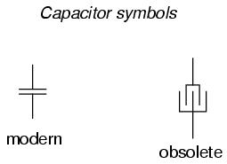
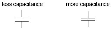
The schematic symbol for a capacitor is quite simple, being little more than two short, parallel lines (representing the plates) separated by a gap. Wires attach to the respective plates for connection to other components. An older, obsolete schematic symbol for capacitors showed interleaved plates, which is actually a more accurate way of representing the real construction of most capacitors:
When a voltage is applied across the two plates of a capacitor, a concentrated field flux is created between them, allowing a significant difference of free electrons (a charge) to develop between the two plates:
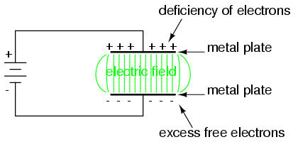
As the electric field is established by the applied voltage, extra free electrons are forced to collect on the negative conductor, while free electrons are "robbed" from the positive conductor. This differential charge equates to a storage of energy in the capacitor, representing the potential charge of the electrons between the two plates. The greater the difference of electrons on opposing plates of a capacitor, the greater the field flux, and the greater "charge" of energy the capacitor will store.
Because capacitors store the potential energy of accumulated electrons in the form of an electric field, they behave quite differently than resistors (which simply dissipate energy in the form of heat) in a circuit. Energy storage in a capacitor is a function of the voltage between the plates, as well as other factors which we will discuss later in this chapter. A capacitor's ability to store energy as a function of voltage (potential difference between the two leads) results in a tendency to try to maintain voltage at a constant level. In other words, capacitors tend to resist changes in voltage drop. When voltage across a capacitor is increased or decreased, the capacitor "resists" the change by drawing current from or supplying current to the source of the voltage change, in opposition to the change.
To store more energy in a capacitor, the voltage across it must be increased. This means that more electrons must be added to the (-) plate and more taken away from the (+) plate, necessitating a current in that direction. Conversely, to release energy from a capacitor, the voltage across it must be decreased. This means some of the excess electrons on the (-) plate must be returned to the (+) plate, necessitating a current in the other direction.
Just as Isaac Newton's first Law of Motion ("an object in motion tends to stay in motion; an object at rest tends to stay at rest") describes the tendency of a mass to oppose changes in velocity, we can state a capacitor's tendency to oppose changes in voltage as such: "A charged capacitor tends to stay charged; a discharged capacitor tends to stay discharged." Hypothetically, a capacitor left untouched will indefinitely maintain whatever state of voltage charge that it's been left it. Only an outside source (or drain) of current can alter the voltage charge stored by a perfect capacitor:
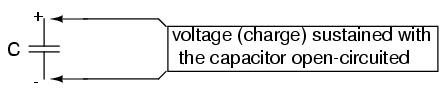
Practically speaking, however, capacitors will eventually lose their stored voltage charges due to internal leakage paths for electrons to flow from one plate to the other. Depending on the specific type of capacitor, the time it takes for a stored voltage charge to self-dissipate can be a long time (several years with the capacitor sitting on a shelf!).
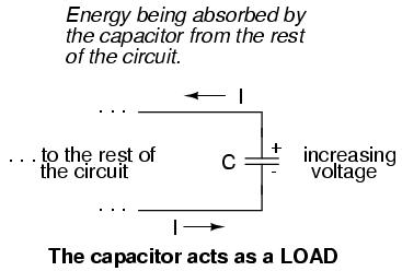
When the voltage across a capacitor is increased, it draws current from the rest of the circuit, acting as a power load. In this condition the capacitor is said to be charging, because there is an increasing amount of energy being stored in its electric field. Note the direction of current with regard to the voltage polarity:
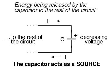
Conversely, when the voltage across a capacitor is decreased, the capacitor supplies current to the rest of the circuit, acting as a power source. In this condition the capacitor is said to be discharging. Its store of energy -- held in the electric field -- is decreasing now as energy is released to the rest of the circuit. Note the direction of current with regard to the voltage polarity:
If a source of voltage is suddenly applied to an uncharged capacitor (a sudden increase of voltage), the capacitor will draw current from that source, absorbing energy from it, until the capacitor's voltage equals that of the source. Once the capacitor voltage reached this final (charged) state, its current decays to zero. Conversely, if a load resistance is connected to a charged capacitor, the capacitor will supply current to the load, until it has released all its stored energy and its voltage decays to zero. Once the capacitor voltage reaches this final (discharged) state, its current decays to zero. In their ability to be charged and discharged, capacitors can be thought of as acting somewhat like secondary-cell batteries.
The choice of insulating material between the plates, as was mentioned before, has a great impact upon how much field flux (and therefore how much charge) will develop with any given amount of voltage applied across the plates. Because of the role of this insulating material in affecting field flux, it has a special name: dielectric. Not all dielectric materials are equal: the extent to which materials inhibit or encourage the formation of electric field flux is called the permittivity of the dielectric.
The measure of a capacitor's ability to store energy for a given amount of voltage drop is called capacitance. Not surprisingly, capacitance is also a measure of the intensity of opposition to changes in voltage (exactly how much current it will produce for a given rate of change in voltage). Capacitance is symbolically denoted with a capital "C," and is measured in the unit of the Farad, abbreviated as "F."
Convention, for some odd reason, has favored the metric prefix "micro" in the measurement of large capacitances, and so many capacitors are rated in terms of confusingly large microFarad values: for example, one large capacitor I have seen was rated 330,000 microFarads!! Why not state it as 330 milliFarads? I don't know.
An obsolete name for a capacitor is condenser or condensor. These terms are not used in any new books or schematic diagrams (to my knowledge), but they might be encountered in older electronics literature. Perhaps the most well-known usage for the term "condenser" is in automotive engineering, where a small capacitor called by that name was used to mitigate excessive sparking across the switch contacts (called "points") in electromechanical ignition systems.
Capacitors do not have a stable "resistance" as conductors do. However, there is a definite mathematical relationship between voltage and current for a capacitor, as follows:
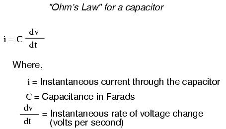
The lower-case letter "i" symbolizes instantaneous current, which means the amount of current at a specific point in time. This stands in contrast to constant current or average current (capital letter "I") over an unspecified period of time. The expression "dv/dt" is one borrowed from calculus, meaning the instantaneous rate of voltage change over time, or the rate of change of voltage (volts per second increase or decrease) at a specific point in time, the same specific point in time that the instantaneous current is referenced at. For whatever reason, the letter v is usually used to represent instantaneous voltage rather than the letter e. However, it would not be incorrect to express the instantaneous voltage rate-of-change as "de/dt" instead.
In this equation we see something novel to our experience thusfar with electric circuits: the variable of time. When relating the quantities of voltage, current, and resistance to a resistor, it doesn't matter if we're dealing with measurements taken over an unspecified period of time (E=IR; V=IR), or at a specific moment in time (e=ir; v=ir). The same basic formula holds true, because time is irrelevant to voltage, current, and resistance in a component like a resistor.
In a capacitor, however, time is an essential variable, because current is related to how rapidly voltage changes over time. To fully understand this, a few illustrations may be necessary. Suppose we were to connect a capacitor to a variable-voltage source, constructed with a potentiometer and a battery:
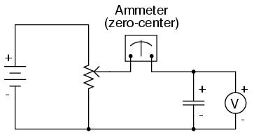
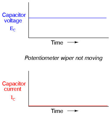
If the potentiometer mechanism remains in a single position (wiper is stationary), the voltmeter connected across the capacitor will register a constant (unchanging) voltage, and the ammeter will register 0 amps. In this scenario, the instantaneous rate of voltage change (dv/dt) is equal to zero, because the voltage is unchanging. The equation tells us that with 0 volts per second change for a dv/dt, there must be zero instantaneous current (i). From a physical perspective, with no change in voltage, there is no need for any electron motion to add or subtract charge from the capacitor's plates, and thus there will be no current.
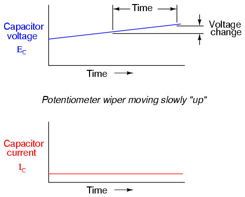
Now, if the potentiometer wiper is moved slowly and steadily in the "up" direction, a greater voltage will gradually be imposed across the capacitor. Thus, the voltmeter indication will be increasing at a slow rate:
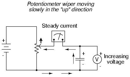
If we assume that the potentiometer wiper is being moved such that the rate of voltage increase across the capacitor is steady (for example, voltage increasing at a constant rate of 2 volts per second), the dv/dt term of the formula will be a fixed value. According to the equation, this fixed value of dv/dt, multiplied by the capacitor's capacitance in Farads (also fixed), results in a fixed current of some magnitude. From a physical perspective, an increasing voltage across the capacitor demands that there be an increasing charge differential between the plates. Thus, for a slow, steady voltage increase rate, there must be a slow, steady rate of charge building in the capacitor, which equates to a slow, steady flow rate of electrons, or current. In this scenario, the capacitor is acting as a load, with electrons entering the negative plate and exiting the positive, accumulating energy in the electric field.
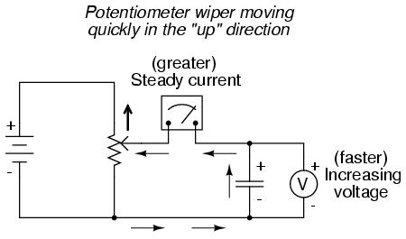
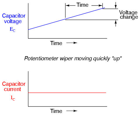
If the potentiometer is moved in the same direction, but at a faster rate, the rate of voltage change (dv/dt) will be greater and so will be the capacitor's current:
When mathematics students first study calculus, they begin by exploring the concept of rates of change for various mathematical functions. The derivative, which is the first and most elementary calculus principle, is an expression of a function's rate of change. Calculus students have to learn this principle while studying abstract equations. You get to learn this principle while studying something you can relate to: electric circuits!
To put this relationship between voltage and current in a capacitor in calculus terms, the current through a capacitor is the derivative of the voltage across the capacitor. Or, in simpler terms, a capacitor's current is directly proportional to how quickly the voltage across it is changing. In this circuit where capacitor voltage can be set by the position of a rotary knob on a potentiometer, we can say that the capacitor's current is directly proportional to how quickly we turn the knob.
If we to move the potentiometer's wiper in the same direction as before ("up"), but at varying rates, we would obtain graphs that looked like this:
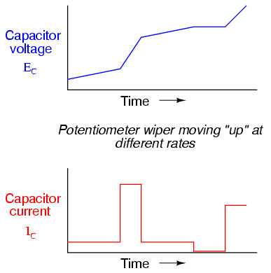
Note how that at any given point in time, the capacitor's current is proportional to the rate-of-change, or slope of the capacitor's voltage plot. When the voltage plot line is rising quickly (steep slope), the current will likewise be great. Where the voltage plot has a mild slope, the current is small. At one place in the voltage plot where it levels off (zero slope, representing a period of time when the potentiometer wasn't moving), the current falls to zero.
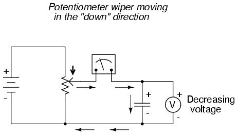
If we were to move the potentiometer wiper in the "down" direction, the capacitor voltage would decrease rather than increase. Again, the capacitor will react to this change of voltage by producing a current, but this time the current will be in the opposite direction. A decreasing capacitor voltage requires that the charge differential between the capacitor's plates be reduced, and that only way that can happen is if the electrons reverse their direction of flow, the capacitor discharging rather than charging. In this condition, with electrons exiting the negative plate and entering the positive, the capacitor will act as a source, like a battery, releasing its stored energy to the rest of the circuit.
Again, the amount of current through the capacitor is directly proportional to the rate of voltage change across it. The only difference between the effects of a decreasing voltage and an increasing voltage is the direction of electron flow. For the same rate of voltage change over time, either increasing or decreasing, the current magnitude (amps) will be the same. Mathematically, a decreasing voltage rate-of-change is represented as a negative quantity for dv/dt. Following the formula i = C(dv/dt), this will result in a current figure (i) that is likewise negative in sign, indicating a direction of flow corresponding to discharge of the capacitor.
There are three basic factors of capacitor construction determining the amount of capacitance created. These factors all dictate capacitance by affecting how much electric field flux (relative difference of electrons between plates) will develop for a given amount of magnetic field force (voltage between the two plates):
PLATE AREA: All other factors being equal, greater plate gives greater capacitance; less plate gives less capacitance.
Explanation: Larger plate area results in more field flux (charge collected on the plates) for a given field force (voltage across the plates).
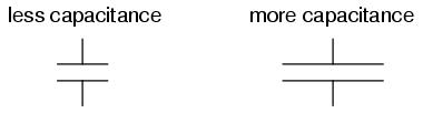
PLATE SPACING: All other factors being equal, further plate spacing gives less capacitance; closer plate spacing gives greater capacitance.
Explanation: Closer spacing results in a greater field force (voltage across the capacitor divided by the distance between the plates), which results in a greater field flux (charge collected on the plates) for any given voltage applied across the plates.
DIELECTRIC MATERIAL: All other factors being equal, greater permittivity of the dielectric gives greater capacitance; less permittivity of the dielectric gives less capacitance.
Explanation: Although it's complicated to explain, some materials offer less opposition to field flux for a given amount of field force. Materials with a greater permittivity allow for more field flux (offer less opposition), and thus a greater collected charge, for any given amount of field force (applied voltage).
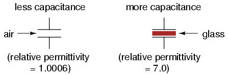
"Relative" permittivity means the permittivity of a material, relative to that of a pure vacuum. The greater the number, the greater the permittivity of the material. Glass, for instance, with a relative permittivity of 7, has seven times the permittivity of a pure vacuum, and consequently will allow for the establishment of an electric field flux seven times stronger than that of a vacuum, all other factors being equal.
The following is a table listing the relative permittivities (also known as the "dielectric constant") of various common substances:
Material        Relative permittivity (dielectric constant)
============================================================
Vacuum ------------------------- 1.0000
Air ---------------------------- 1.0006
PTFE, FEP ("Teflon") ----------- 2.0
Polypropylene ------------------ 2.20 to 2.28
ABS resin ---------------------- 2.4 to 3.2
Polystyrene -------------------- 2.45 to 4.0
Waxed paper -------------------- 2.5
Transformer oil ---------------- 2.5 to 4
Hard Rubber -------------------- 2.5 to 4.80
Wood (Oak) --------------------- 3.3
Silicones ---------------------- 3.4 to 4.3
Bakelite ----------------------- 3.5 to 6.0
Quartz, fused ------------------ 3.8
Wood (Maple) ------------------- 4.4
Glass -------------------------- 4.9 to 7.5
Castor oil --------------------- 5.0
Wood (Birch) ------------------- 5.2
Mica, muscovite ---------------- 5.0 to 8.7
Glass-bonded mica -------------- 6.3 to 9.3
Porcelain, Steatite ------------ 6.5
Alumina ------------------------ 8.0 to 10.0
Distilled water ---------------- 80.0
Barium-strontium-titanite ------ 7500
An approximation of capacitance for any pair of separated conductors can be found with this formula:
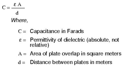
A capacitor can be made variable rather than fixed in value by varying any of the physical factors determining capacitance. One relatively easy factor to vary in capacitor construction is that of plate area, or more properly, the amount of plate overlap.
The following photograph shows an example of a variable capacitor using a set of interleaved metal plates and an air gap as the dielectric material:
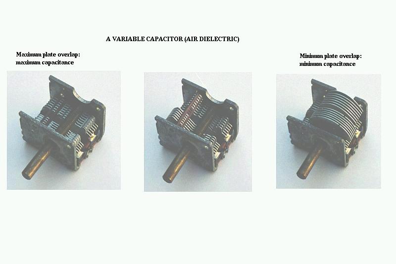
As the shaft is rotated, the degree to which the sets of plates overlap each other will vary, changing the effective area of the plates between which a concentrated electric field can be established. This particular capacitor has a capacitance in the picofarad range, and finds use in radio circuitry.
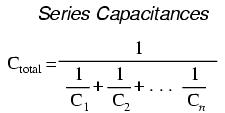
When capacitors are connected in series, the total capacitance is less than any one of the series capacitors' individual capacitances. If two or more capacitors are connected in series, the overall effect is that of a single (equivalent) capacitor having the sum total of the plate spacings of the individual capacitors. As we've just seen, an increase in plate spacing, with all other factors unchanged, results in decreased capacitance.
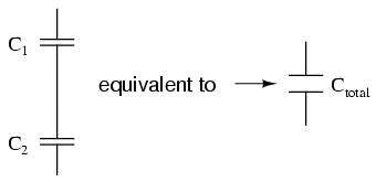
Thus, the total capacitance is less than any one of the individual capacitors' capacitances. The formula for calculating the series total capacitance is the same form as for calculating parallel resistances:
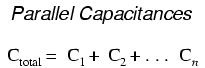
When capacitors are connected in parallel, the total capacitance is the sum of the individual capacitors' capacitances. If two or more capacitors are connected in parallel, the overall effect is that of a single equivalent capacitor having the sum total of the plate areas of the individual capacitors. As we've just seen, an increase in plate area, with all other factors unchanged, results in increased capacitance.
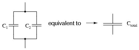
Thus, the total capacitance is more than any one of the individual capacitors' capacitances. The formula for calculating the parallel total capacitance is the same form as for calculating series resistances:
As you will no doubt notice, this is exactly opposite of the phenomenon exhibited by resistors. With resistors, series connections result in additive values while parallel connections result in diminished values. With capacitors, it's the reverse: parallel connections result in additive values while series connections result in diminished values.
Capacitors, like all electrical components, have limitations which must be respected for the sake of reliability and proper circuit operation.
Working voltage: Since capacitors are nothing more than two conductors separated by an insulator (the dielectric), you must pay attention to the maximum voltage allowed across it. If too much voltage is applied, the "breakdown" rating of the dielectric material may be exceeded, resulting in the capacitor internally short-circuiting.
Polarity: Some capacitors are manufactured so they can only tolerate applied voltage in one polarity but not the other. This is due to their construction: the dielectric is a microscopically thin layer if insulation deposited on one of the plates by a DC voltage during manufacture. These are called electrolytic capacitors, and their polarity is clearly marked.
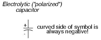
Reversing voltage polarity to an electrolytic capacitor may result in the destruction of that super-thin dielectric layer, thus ruining the device. However, the thinness of that dielectric permits extremely high values of capacitance in a relatively small package size. For the same reason, electrolytic capacitors tend to be low in voltage rating as compared with other types of capacitor construction.
Equivalent circuit: Since the plates in a capacitors have some resistance, and since no dielectric is a perfect insulator, there is no such thing as a "perfect" capacitor. In real life, a capacitor has both a series resistance and a parallel (leakage) resistance interacting with its purely capacitive characteristics:
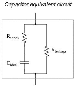
Fortunately, it is relatively easy to manufacture capacitors with very small series resistances and very high leakage resistances!
Physical Size: For most applications in electronics, minimum size is the goal for component engineering. The smaller components can be made, the more circuitry can be built into a smaller package, and usually weight is saved as well. With capacitors, there are two major limiting factors to the minimum size of a unit: working voltage and capacitance. And these two factors tend to be in opposition to each other. For any given choice in dielectric materials, the only way to increase the voltage rating of a capacitor is to increase the thickness of the dielectric. However, as we have seen, this has the effect of decreasing capacitance. Capacitance can be brought back up by increasing plate area. but this makes for a larger unit. This is why you cannot judge a capacitor's rating in Farads simply by size. A capacitor of any given size may be relatively high in capacitance and low in working voltage, visa-versa, or some compromise between the two extremes. Take the following two photographs for example:
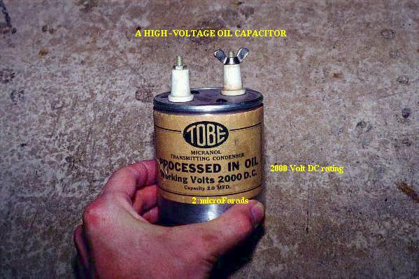
This is a fairly large capacitor in physical size, but it has quite a low capacitance value: only 2 µF. However, its working voltage is quite high: 2000 volts! If this capacitor were re-engineered to have a thinner layer of dielectric between its plates, at least a hundredfold increase in capacitance might be achievable, but at a cost of significantly lowering its working voltage. Compare the above photograph with the one below. The capacitor shown in the lower picture is an electrolytic unit, similar in size to the one above, but with very different values of capacitance and working voltage:
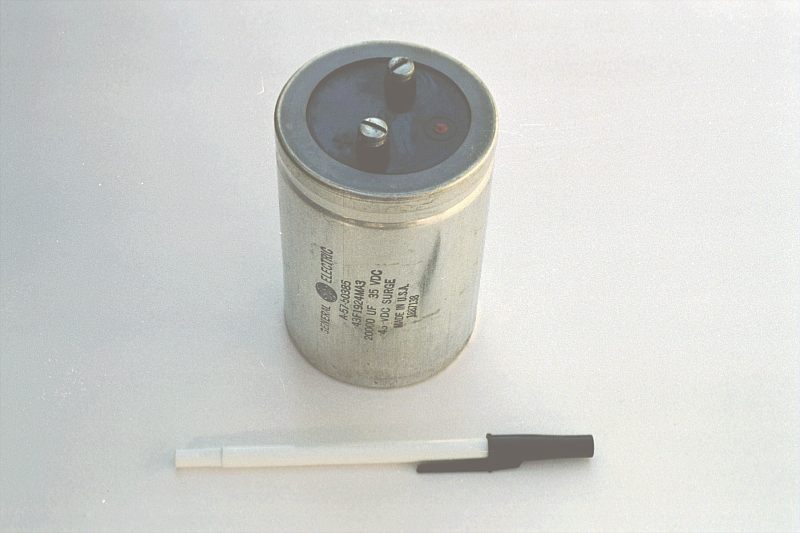
The thinner dielectric layer gives it a much greater capacitance (20,000 µF) and a drastically reduced working voltage (35 volts continuous, 45 volts intermittent).
Here is a sample of different capacitor types:
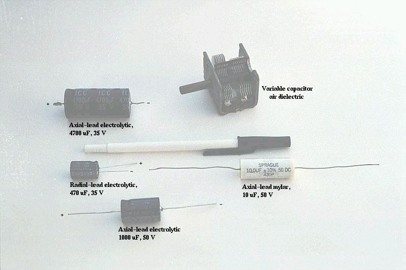
The electrolytic capacitors are polarity-sensitive, and are labeled as such. The dark units in the above photograph have their negative (-) leads distinguished by arrow symbols on their cases. The 20,000 µF electrolytic unit in the previous photograph has its positive (+) terminal labeled with a "plus" mark. Note how neither the mylar nor the air dielectric capacitors in the photograph above have polarity markings, because neither type is polarity-sensitive.
Capacitors come in very small sizes as well. Take a close look at the following photograph. Every component marked with a "C" designation on the printed circuit board is a capacitor:
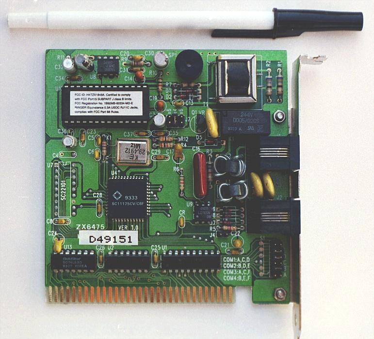
Some of the capacitors shown on this circuit board are standard electrolytic: C30 (top of board, center) and C36 (left side, 1/3 from the top). Some others are a special kind of electrolytic capacitor called tantalum, because this is the type of metal used to make the plates. Tantalum capacitors have relatively high capacitance for their physical size. The following capacitors on the circuit board shown above are tantalum: C14 (just to the lower-left of C30), C19 (directly below R10, which is below C30), C24 (lower-left corner of board), and C22 (lower-right).
Examples of even smaller capacitors can be seen in this photograph:
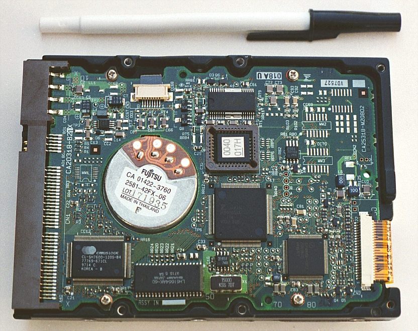
The capacitors on this circuit board are "surface mount devices" as are all the resistors, for reasons of saving space. Following component labeling convention, the capacitors can be identified by labels beginning with the letter "C".